-
-
August 21, 2018 at 6:08 pmConnorMcGladeSubscriber
Hello,
I am trying to model a timber frame shear wall panel. I get a few warnings and an error shown below:
I am using springs to simulate the members and sheathing being connected together. I have a feeling my issue is to do with the constraint set up. I want the bottom framing member to be fixed to the 'floor' and the rest of the members to simulate being connected together by nails. I don't want the panel to move out of plane. I do want the 'nailed' connections to have some degree of movement as it would in real life hence why I have used spring contacts.
Can anyone help me understand why the model will not solve?
-
August 21, 2018 at 8:41 pmpeteroznewmanSubscriber
Hello Connor,
I can help you, and I can be more effective if you put UniHeriot WattResearch DissertationANSYS ModelsInventor ModelsAssembly1.stp into a zip file and attach that to your reply. Without this file, I can't show you how the geometry can be modified to make the model building a lot better.
Beams would better represent the nails than springs and there is a much cleaner way to do them, and that is by imprinting the Stud cross-section onto the Top and Bottom Rails. That way, instead of one end of the spring being scoped to the entire length of the Bottom Rail, it will just be scoped to the little piece of the Bottom Rail that is touching the Stud above it.
However, I notice that you also have Bonded Contact between the Studs and the Top and Bottom Rails. That is doubling up on what the beams are doing, so it would be better to delete the contact between the Studs and the Top and Bottom Rails. The beams will prevent them from penetrating each other, and they are free to tip and tilt on each other by bending the beam.
The Remote Force loads are all scoped to the same vertex, though they have different Z coordinates. This is the wrong way to go about loading the structure. Please describe what you want to accomplish and I will recommend how you can achieve that loading.
Regards,
Peter
-
August 21, 2018 at 9:45 pmConnorMcGladeSubscriber
Hi Peter,
I have attached the new files above.
How do you imprint the stud cross-section on the top and bottom rails? Is this the correct way to model this fixing, by using a spring? or is it better to actually model the nails?
You are correct yes that is what I should do for the bonded contacts.
I would like to have a point load aligned with each stud acting on the top rail above of 4.8kN
Regards
Connor
-
August 22, 2018 at 11:13 ampeteroznewmanSubscriber
Hi Connor,
When you say "point load" I understand what you mean, but that does not literally translate into load on a vertex. It is best to apply loads in a solid element model (as opposed to shell models on surfaces) on a face, and second best to an edge. Try to avoid applying loads to a vertex. However, relative to the overall size of the wall, picking an edge or face of the stud is very localized to the stud.
Imprinting
Right click on Geometry cell in Workbench and Edit in DesignModeler. Click Generate (F5). Expand the 19 Parts, 19 Bodies line in the Tree Outline. Pick all the parts in the DesignModeler outline, and RMB to Form New Part. Now you have 1 Part, 19 Bodies.
At this stage, the parts are going to be "glued together" during meshing. This is sometimes what you want, but in this case, you want to change the Shared Topology Method default from Automatic to Imprints. That will create a face on the long bottom and top rails at each stud. Close DM and Refresh Project in Workbench to bring the new geometry into the Model. Open the Model.
Now in Mechanical, you can create a Beam between the face on the rail and the face on the stud.
When you click the face, it puts one end of the beam on that face, but subtract off 0.3" (or add on the top rail) to offset the beam end, since the other end of the beam is going to be defined on a coincident face on the stud and you can't have a zero length beam. Add 0.3" to the bottom of the stud (or subtract on the top of the stud). Now you have a 0.6" long beam and that beam can bend with the stiffness of a steel cylinder that you define, maybe 0.05"
Since the beam is very stiff along its axis, there is no need for contact on the top or bottom of the studs to the rails.
What version of ANSYS are you using? Attached is an ANSYS 19.1 archive.
Regards,
Peter
-
August 22, 2018 at 7:21 pmConnorMcGladeSubscriber
Hi Peter,
I have modeled the beams in place of the springs but it appears it does not allow the stud and the bottom rail to spererate as it would in reality. Is this because the beam is too stiff or should it be a spring? As I would also like to fix the Sheathing to the studs either using a beam or spring. The connection between the stud and bottom and top rail is really only taking axial loads and the connection between the sheathing and stud is lateral loads, should these connections differ due to their loading? Also, the beam does not allow for a stiffness to be input but the spring does?
As for the vertical loads. I understand what you mean, but the vertical loads should be acting downwards through the centroid of each stud but should be applied to the top rail, above each stud. if that makes sense?
Above is the standard im trying to replicate. Ie the vertical loads.
Also is there any way I can speed up the analysis?
Regards
Connor
-
August 23, 2018 at 3:22 ampeteroznewmanSubscriber
Hi Connor,
Using short beams allows the studs to rotate about each end. For example, with just the bottom rail and one stud connected with a beam, I can apply 0.25 lbf to the top of the stud and see a 10” displacement at the top.
The beam is acting as a spring. The 0.25 lbf for the 10" deflection was for a beam with a 0.05" radius. If you change the radius to 0.1" then the force to deflect 10" becomes 2.0 lbs and the stud starts to show some flexing. So the beam diameter and length control its spring rate. There are beam bending formulas if you want to know the exact spring rate.
If you zoom in on the bottom of the stud, you will see it is rotating.
This is not exactly what you want, you could offset the beam to align with the edge of the stud.
Here the beam was at the center of the face:
Now it is offset to the edge of the stud.
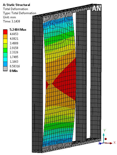
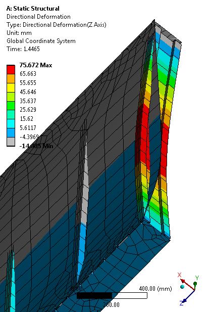
Here is the deformation of 10" at the top.
If you used Frictional Contact, you could get the same effect, but that would slow down the simulation.
The best way to speed up the simulation would be to change the sheathing from a solid model to a Mid-Surface. Then the sheathing is meshed with shell elements that are assigned the thickness of the sheathing. I have done that for one OBS panel.
Another way to speed up the simulation is if you have multiple cores on your computer.
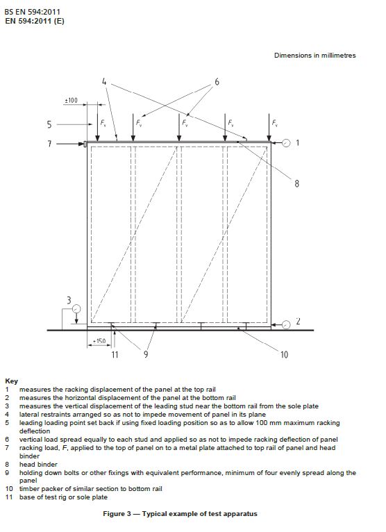
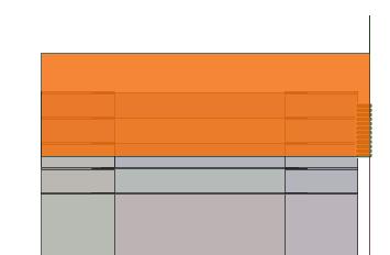
The way to apply force to the top rail is to use DesignModeler. Create a plane on the top, create a sketch on that plane, and use a Face Split. I have done that at a 100 mm dimension from the end as shown in the Standard. This creates a line to apply the load to in Mechanical. You can see the Surface of the sheathing in the image below.
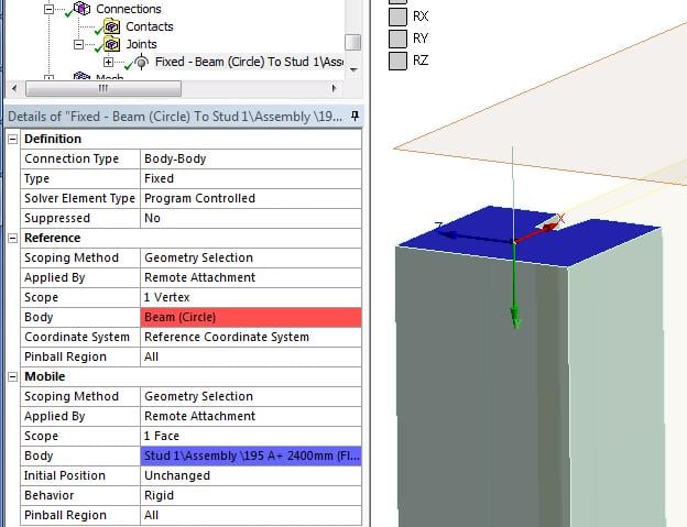
You can use beams to connect the sheathing to the frame. You need to create a point on the midsurface that represents the sheathing. While you can connect a beam to a point on a shell element on a surface, special consideration is needed to connect a beam to a solid element node on a vertex of the solid.
Beam and shell elements have nodes with six degrees of freedom: 3 translations and 3 rotations. Solid element nodes have only 3 translation degrees of freedom. If you cantilever a beam element off a shell, it will support load. If you cantilever a beam element off one node on a solid, it will fall over, since there is no rotational stiffness on a single node on the solid element. However since one end of the beam is on the shell, this may work for your model. (When you have to cantilever beams off of solids, you have to pick a face and make a bonded contact between the face and the beam vertex.)
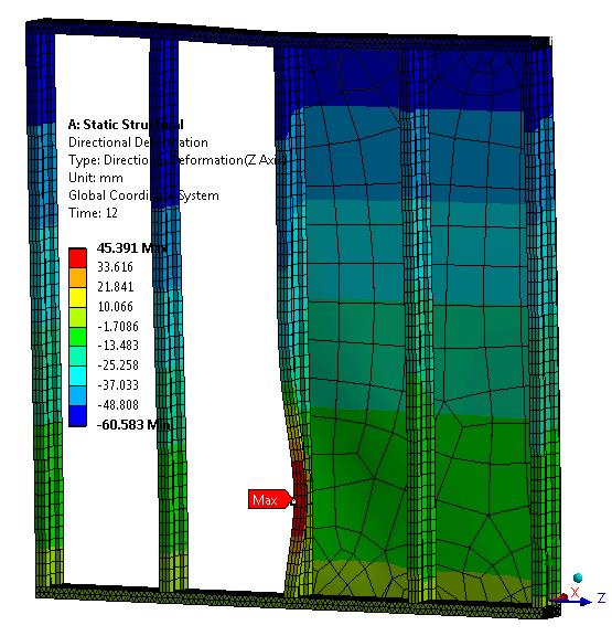
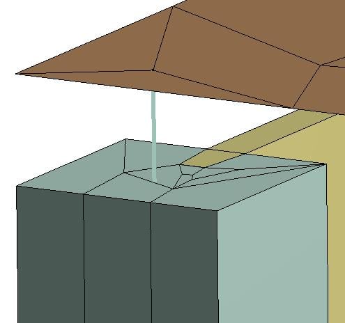
Use DesignModeler to create a point on each side by creating planes to slice the sheet and rail and stud along their centerplanes where I imagine a nail would go. In the image below, I have hidden the face of the surface body in the corner of the sheathing to show the beam going between the two vertices.
The top rail is now 4 bodies, so they need to be put in their own part. The stud is now 2 bodies, so put them along with the web and the other stud into a part called Stud1. With Shared Topology set to Automatic for Stud1, those bodies will be held together by sharing common nodes at the coincident faces, so there is no need for bonded contact to hold them together. That will speed up your simulation slightly.
However, now the Imprints described in the previous post can't be used to cut out a small piece of the bottom rail. Instead, create a plane and make a sketch to use Face Split to form a rectangle at the bottom of the stud for the beam to be connected.
Finally, I added two Remote Displacements. The each have zero displacement for the X coordinate. Those act as the lateral supports allowed for in the Standard, and one of them is the Racking Load, which is input as a displacement. You use the Force Reaction to measure how much force is used to rack that end by the entered displacement.
That is a lot to absorb. Good luck!
Regards,
Peter
-
August 23, 2018 at 9:44 pmConnorMcGladeSubscriber
Hi Peter,
Thank you again for your very detailed response! I must admit a lot of that has gone over my head, I'm self-taught at this so learning as I go along.
I agree the beams work, although I'm just curious as to why they are better than using springs? If I were to add two beams either side of the stud to stop it rotating completely would this, in theory, be doubling the stiffness of the connection? and also increasing computing time?
Now here is where I get lost, how do we convert the OSB from a solid model to a surface and then mesh it with shell elements? I inserted a midsurface but it then invalidated the rest of the parts?
I think once I understand how to convert the OSB to surfaces, then things will become clearer. As I will need to model nails connecting the sheathing to the frame at 50mm spacings I think things could get complicated here.
I have tried to model the beams for the connections on the studs but get an error, what is this due to? see attached
Many thanks for your help thus far!
Regards
Connor
-
August 24, 2018 at 2:38 ampeteroznewmanSubscriber
Hi Connor,
Springs create a tension (or compression) force along the line between the two end points. Say the spring is vertical with 1" between the ends and the bottom end is fixed. If I move the top end up by 0.1" to make the spring 1.1" long, that will generate a force of 0.1*K lbs, where K is the stiffness in lbs/in. But if I move the top end sideways by 0.1", then the length of the spring was only stretched to a length of 1.005" and the force between the ends is only 0.005*K lbs. That is not very useful for stopping sideways motion.
Beam are very stiff along their axis, won't go sideways easily, but will bend, so they are perfect for what you want. Beams are very cheap to compute. Beams that are connected to faces lock rotation, so you don't need two beams to prevent the stud-web-stud assembly from rotating around the beam like you would if there was just one nail. If you use two beams like you would use two nails, then you will double the bending stiffness in the direction perpendicular to the two beams. The bending stiffness in the plane of the two beams just became huge. Adding the second beam greatly increases the torsional stiffness of rotating the stub-web-stud assembly around its long axis.
Since you need 50 mm spacing on the nails of the OSB to the frame, it may be better to create line bodies in DesignModeler using a pattern feature. Then use shared topology to connect the line bodies to the OSB and Frame. That will be less work. The line bodies become beams in Mechanical.
I will make a short video on how to convert the OSB from a solid to a shell. Whenever you make geometry changes after you have built things in Mechanical, like beams and things, they do get broken when the new geometry comes in, which is why it is good to have a plan and work on the geometry first.
Regards,
Peter
-
August 26, 2018 at 1:54 ampeteroznewmanSubscriber
Hi Connor,
Here is a video on how to create a midsurface in SpaceClaim and a row of beam elements to represent the nails.
https://youtu.be/8w5RkJe6I9A
You can show your appreciation by clicking Like below the posts that are helpful.
-
August 26, 2018 at 2:20 ampeteroznewmanSubscriber
In this video, Shared Topology is used to connect the beams to the sheet and solid.
Also, I see you have orthotropic material for the wood. This requires that you define two coordinate systems where each x-axis points along the length of the rail and spar respectively, so that the high stiffness axial direction of the grain is properly used.
https://youtu.be/3L1ww4IKVP0
You can show your appreciation by clicking Like below the posts that are helpful.
-
August 30, 2018 at 11:41 amConnorMcGladeSubscriber
Hi Peter,
Sorry for the slow reply, your videos have been extremely useful, I've followed them both through fairly easily, although when I come to the last stage my mesh appears to be solid and not a surface, why is this, is it something visual or something i havnt done?
I really do appreciate the time you've taken here to create these solutions!
I have attached my archive
-
August 30, 2018 at 5:56 pmpeteroznewmanSubscriber
Hi Connor,
Under Mesh Details, I set the element order to Linear to get rid of the Mixed Mode warning. I don't know if that was required or not.
I also saw that the nails only fasten the first sheet to the rails, so I suppressed the second sheet.
I fixed up the BCs and it ran. Were you going to run some nails down the studs?
Regards,
Peter
-
August 30, 2018 at 6:38 pmConnorMcGladeSubscriber
Hi Peter,
My model seems to be taking a while to solve, changing to linear has stopped that error, could the long solve time be due to contacts? I still have bonded contacts between the flanges and the top and bottom rails, is this correct? I also have had to suppress bonded contacts between flange and OSB but your model did not appear to have these?
Yes the intention is to have nails running the perimeter studs and rails as well as the internal studs. I then plan on creating several models with difference nail spacings i.e 50mm, 100mm and 150mm.
I have tried to run the analysis but it seems to be something to do with my constraints although its seems to be restained fine to me, im not sure why it wont solve.
I have attatched the file
Regards
Connor
-
August 30, 2018 at 7:31 pmpeteroznewmanSubscriber
Hi Connor,
You need the bonded contact between the Rails and the Studs, but you can replace that with beams like we did at the very beginning.
I did suppress the bonded contact between the Flange and the OSB since it was connected with nails at the top and the bottom rails. You can run it with that contact on for a different result.
How many cores does your computer have?
Regards,
Peter
-
August 30, 2018 at 7:55 pmConnorMcGladeSubscriber
Hi Pete,
I thought that, that makes sense to me. Would you mind looking at the attatched file above and seeing why it will not solve?
I'm currently running 4 cores.
Regards
Connor
-
August 30, 2018 at 11:16 pmpeteroznewmanSubscriber
Hi Connor,
Click on Solution Information and in the details window, type 3 for Newton-Raphson Residuals. Then click Solve. After solving, there will be 3 plots under the Solution Information folder. The maximum value on those plots shows you the location where the solver can't get convergence. It needs more elements at that location. Add mesh controls to make smaller elements at the location of the maximum N-R Residual plot. I will reply with that plot that when it finishes solving.
Regards,
Peter
-
August 31, 2018 at 12:07 ampeteroznewmanSubscriber
You may have seen by now that the problem was along the top rail. It will be best if there are two elements through the thickness of the top rail.
Click on Mesh Details, and under the Sizing Branch, set Adaptive to No, then lower down, set Proximity to Yes, then for Number of Elements across gap set that to 2. And set the Proximity Min Size to 10 mm.
Then you get a good mesh on the top rail. Then you must add an Edge Sizing on all the edges of the Studs. Use the Box Select method. You have to set the Behavior to Hard to get it to take.
-
August 31, 2018 at 12:43 amConnorMcGladeSubscriber
Hi Peter,
I tried that but I still get the same issue?
Regards
Connor
-
August 31, 2018 at 2:09 amJimmyhanSubscriber
Hi Peter, I need your help, why not give me some suggestion for my simulation./forum/forums/topic/set-source-and-source-coefficient-in-mass-transfer-simulation/?postbadges=true
-
August 31, 2018 at 2:21 ampeteroznewmanSubscriber
Hi Jimmy,
I only know Structural simulations. I'm very much a beginner at this CFD stuff, especially with concentrations and mass transfer.
Fortunately, there are lot's of ANSYS experts on the site now!
Good luck, and please delete your post from this discussion.
I hope I can help next time.
Kind regards,
Peter
-
August 31, 2018 at 2:30 ampeteroznewmanSubscriber
Hi Connor,
You didn't request 2 elements across the gap, only 1. You can also change back to Quadratic Element Order, that helps it to finish.
You are slowing down your solution somewhat by requiring 12 steps to get to the final load of 54 kN. Each step by default is taking 4 substeps to get there. If instead you only requested 4 steps of 13.5 kN each increment, it might get to the final load with less total increments.
Looks like one of the studs is buckling.
Regards,
Peter
-
August 31, 2018 at 10:28 amConnorMcGladeSubscriber
Hi Peter
Thanks for that, I'm struggling at the moment to try and get the nodes/elements under 32k, I think i may need to do some fiddling about to get a mesh that works under 32k
Connor
-
August 31, 2018 at 2:05 pmConnorMcGladeSubscriber
Hi Peter,
I've tried to no avail to get the nodes under my student limit. Is there any other way of modelling this to further reduce the problem size? I'm aware I'm already exceeding the limit without both sheathing parts. Could using the beams be using up too many nodes/elements?
Regards
Connor
-
August 31, 2018 at 8:57 pmpeteroznewmanSubscriber
Hi Connor,
In fact, beams are the most efficient way to model a structure. Using mid-surface models is the second most efficient and using solids is the least efficient way to model a structure, in terms of minimizing node count.
You should replace the top and bottom rails with sheet bodies at the mid-surface. Just keep the Studs, which are meshing very efficiently. However, the bottom rail is Fixed to ground, so just eliminate the bottom rail and connect the bottom of each Stud to ground either with a Fixed Support, or a Beam!
Regards,
Peter
-
September 2, 2018 at 5:10 pmConnorMcGladeSubscriber
Hi Peter,
That sounds like a good idea, whats your thoughts on going a step further and changing the webs in the studs to sheet bodies?
I'll let you know how I get on!
Kind Regards
Connor
-
September 2, 2018 at 5:50 pmpeteroznewmanSubscriber
Hi Connor,
Connecting sheet bodies to solid bodies requires some care due to the fact that nodes on solid elements don't support rotations. It would be better to generate three sheets, assign a large thickness to the flanges and assign a small thickness to the web. If those three sheets are in a multibody part, then Shared Topology will connect them with shared nodes at the common edge. In bending and twisting, these three sheets will respond very similarly to the solid body version.
Regards,
Peter
-
September 2, 2018 at 11:07 pmConnorMcGladeSubscriber
Hi Peter,
I think deleting the bottom rail then adding beams can be my next move!
I'm trying to get the mesh right for this model now but still is not working, its now giving me the error that my node count is higher than 32k. Both my elements and nodes are less than 32k combined. I've seen your other thread about updating the geometry from source but still not working, I've shut the program down and opened it back up as well as clearing data and still is not working. What is wrong with the model?
Kind Regards
Connor
-
September 2, 2018 at 11:31 pmpeteroznewmanSubscriber
Hi Connor,
When I run your model on a Full License, here is the summary.
--- Number of total nodes = 28239
--- Number of contact elements = 81988
--- Number of spring elements = 0
--- Number of bearing elements = 0
--- Number of solid elements = 25403
--- Number of condensed parts = 0
--- Number of total elements = 107391
The contact elements are causing your model to exceed the 32,000 element limit. They aren't created in Mechanical so you can't see them till the solver runs, then they are created, pushing your model over the limit.
If you delete all these bonded contacts, the solver will start.
However, the solver will fail because you need to add some beams to connect the studs to the OBS and to the rails.
You still have a row of nails on the top and bottom that you don't need. The bottom nails because the bottom rail is gone. The top nails because the top rail is sharing topology with the OBS as shown by the purple line at the intersection.
I reduced the mesh density and put back one bonded contact of top rail to studs and this will run. Archive 19.1 attached.
Kind regards,
Peter
-
September 3, 2018 at 9:53 pmConnorMcGladeSubscriber
Hi Pete
Thanks for that, I got that to run!
Although now the top rail and OSB are now bonded, this does not replicate a nailed connection, is there a way of now replicating this?
I have tried now putting beams to connect the studs to the ground rather than a fully fixed connection, but this is now causing me to exceed the problem limit. How can i get round this? I feel like were so close this now!! My aim is to get a model with sheathing fixed to the studs replicating a nailing pattern around the perimeter of both sheets an the studs being connected to the ground using beams so there is a stiffness on the uplift forces. Is this going to be possible with my size of model?
Kind Regards
Connor
-
September 3, 2018 at 11:23 pmpeteroznewmanSubscriber
Hi Connor,
You made the surface wider than the top rail. There is supposed to be a gap between the top rail and the midsurface of the OSB, but you made them touch.
Make the midsurface for the top rail equal to the width of the top rail and you will get the gap back and can use the nails to connect the two midsurfaces.
You can reduce the mesh density on the OSB and the Top Rail. If you have to, you can convert the studs into surfaces as described in a previous post. In that way you can certainly have a model that runs in the Student license limits.
Here are two studs, one has been converted into a midsurface model, with two different thickness assignments.
I used Combine on the three solids to make them one before I used Midsurface.
Regards,
Peter
-
September 3, 2018 at 11:51 pmConnorMcGladeSubscriber
How can I change the size of the surface?
-
September 4, 2018 at 12:00 ampeteroznewmanSubscriber
Make that surface the Active Component.
Click on the Pull Tool
Pick the Edge you want to move
Type U to use the Up To feature
Click on the side of a Stud.
The Top Rail will be level with the edge of a Stud.
-
September 4, 2018 at 12:59 amConnorMcGladeSubscriber
Hi Peter,
I've added in some extra nails again for the studs and the other OSB. I now appear to get a pivot warning, why is this? Is it something I haven't restained?
See attatched
Kind Regards
Connor
-
September 4, 2018 at 1:15 ampeteroznewmanSubscriber
Hi Connor,
The problem is the Beam is not connected to the Stud.
You can add a fixed joint between the end of the beam and the face of the stud.
Do this for the 10 beams at the top of the studs and the 10 beams at the bottom of the studs. There is some automation called the Object Generator that could do this, but you have to do some setup to make it run.
Kind regards,
Peter
-
September 4, 2018 at 1:36 ampeteroznewmanSubscriber
Here you go, I made the 20 joints with some automation, but you need contact now.
I added Bonded contact to prevent the OSB from penetrating the Studs. You could add beams instead to simulate nails.
It solves to the end, but you have to do research on how to get the orthotropic material X direction to go along the top rail now that it is a shell mesh instead of a solid mesh. Here is a relevant post.
ANSYS 19.1 archive attached.
-
September 9, 2018 at 3:45 ampeteroznewmanSubscriber
Hi Connor,
I made a video to show how to use the Object Generator to quickly make 20 Fixed Joints to connect the beam vertex to the stud face.
I put it in the Tutorial section so that it might be found by people looking for Object Generator.
Regards,
Peter
-
October 10, 2018 at 7:54 pmConnorMcGladeSubscriber
Hi Peter,
Your help has been incredible thus far, sorry for the long reply, I started a new job the day after my last post. Coming back to this now for the final push.
Connor
-
October 11, 2018 at 4:27 ampeteroznewmanSubscriber
Hi Connor,
No problem. Please start a new discussion for the next set of questions.
Regards,
Peter
-
March 9, 2021 at 2:33 pmSmileyniallSubscriberHi,n I was wondering if these same princeiples could be applied to a screw instead of a nail? I am also currently doing a project on the racking resistance of a timber frame structure and was looking for a way to attach sheetingboard using screws and was also told about springs but, this method with beams seems better.n
-
- The topic ‘Ansys 19.1 – Timber frame shear wall using spring connections’ is closed to new replies.
-
1882
-
802
-
599
-
591
-
366
© 2025 Copyright ANSYS, Inc. All rights reserved.