-
-
August 17, 2018 at 9:17 am
KumarVaibhav
SubscriberI am unable to generate mesh for the following geometry attached.I was earlier able to do generate owing to guidance from Peter wherein midsurface property was used however it is not possible for me to do the same again.Need urgent help please find the cad attached
-
August 17, 2018 at 9:19 am
KumarVaibhav
Subscriberi am on ansys 16.0 version and cant get an update as our institute provides latest version upto 16 only.IF ANYBODY RESOLVES THE MESH PLS TAKE DUE CARE SO THAT I AM ABLE TO OPEN BACK THE FILE IN MY PROJECT
Â
-
August 17, 2018 at 10:15 am
Karthik Remella
AdministratorHello Kumar,
There are couple of points I'd like to make here.
- This community is meant for providing guidance in order to point people in the correct direction, and is not meant for obtaining files with completed analysis. The whole exercise is designed for active exchange of ideas and to promote learning.
- When you attach a file, only non-ANSYS employee might be able to open them. If you want best use out of this community, I'd suggest you take some screenshots and succinctly explain your issue so someone is able to point you in the right direction.
Please explain the nature of your issue here (with necessary screenshots) so you might find the appropriate help to resolve your problem.
Thank you.
Best Regards,
KarthikÂ
Â
-
August 17, 2018 at 11:26 am
KumarVaibhav
SubscriberkARTHIK I UNDERSTAND THE COMMUNITY PRINCIPLES HOWEVER IT IS ATTACHED TO JUST LOOK AT THE ACTUAL STATE AND REASONS WHY MESHING FAIILS.aS A LEARNER IT ISNT POSSIBLE FOR ME TO QUESTION AND POST SCREENSHOTS AS IT MIGHT BE MISLEADING FOR THE EXPERTS TO SEE.IT IS IN THIS EXCHANGE OF IDEAS IN BETTER WAYS I RESORT TO ATTACHING FILES SO THAT EXPERST CAN OPEN AND CITE ME THE ACTUAL REASON WHICH I AM IGNORANT OF.yOU CAN SEE THAT FROM MY PREVIOUS POSTS,PLS TRY TO COOPERATE AN UNDERSTAND IF HAD I KNOWN THE TECHICALITIES WOULDNT HAVE BEEN TYPING SO MUCH HERE.
-
August 17, 2018 at 12:26 pm
Rob
Forum ModeratorHi Kumar,Â
However if you don't post images no one at ANSYS can tell you anything: as Karthik says, we can't open projects or other ANSYS software due to the constraints we're working under. Images however we can look at. Error messages are also (sometimes) useful.Â
Cheers,
Rob -
August 17, 2018 at 1:41 pm
peteroznewman
SubscriberHi Kumar,
I don't work for ANSYS, so I can open files and provide whatever guidance I want. I participate on this site in my spare time for fun. When I go to work I can't be on this site, so you have to wait.
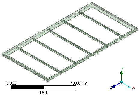
1) The "bed frame" body should have been created in CAD as six solid bodies, not one. That will make it much easier to create the five cross-beams, separate from the rectangular frame. Recreate this body in CAD without Unite-ing six bodies into one.
2) In DesignModeler, When you use Tools > Mid-Surface, click and shift click the two faces, you get this popup:
After entering the suggested Tolerance value, and knowing the thickness is 0.005 m, the face pair can be made.
After Ctrl-clicking the four faces of this solid, a Mid-Surface is successfully generated.
Â
I expect you can make the same Mid-Surface yourself, and also the six bodies that make up the bed frame once you undo the unite operation in the CAD system.
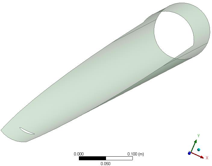
The tedious part is to make the leaf part, which has 263 faces. I recommend you don't bother to midsurface the leaf part, which is only 2 mm thick. In the CAD system, extract the faces off the inside (top) of the leaf solid, and delete the leaf solid before exporting the geometry. You should Sew those faces into a single body in the CAD system if possible.
What CAD system was used to generate these solid models?
If you need more help, please reply with a Workbench Project Archive .wbpz file that has at least the seven Mid-Surface features described above
Also, please reply WITHOUT USING ALL CAPS.
Regards,
Peter
-
August 17, 2018 at 3:06 pm
KumarVaibhav
Subscriberpeter it was made using solidworks but this time after applying repair options from tool i was able to generate the mesh.thanks for help again brother.
-
August 17, 2018 at 6:39 pm
peteroznewman
SubscriberDo you mean a mesh on a solid body or a surface body?
-
August 18, 2018 at 9:27 am
KumarVaibhav
Subscriberyes on the solid body after i suppressed the surface ones
-
August 18, 2018 at 11:34 am
peteroznewman
SubscriberBut Kumar, weren't you trying to get surface bodies to replace the solid bodies?
What type of analysis are you doing with this mesh? We have established that for a Structural simulation, a solid mesh is not appropriate and a shell mesh is best for the leaf part that is only 2 mm thick and more than 1000 mm long.
-
August 18, 2018 at 11:44 am
KumarVaibhav
SubscriberActually i shall be using the solid part the frame to see its response when one end fixed and 25 kg mass distributed over it just like a cantilever.The surface bodies represent the clad that i intend to use so i am trying to see what results i do get.i TRIED USING THE SURFACE BUT IT FAILS SO I SWITCHED TO IT.
-
August 18, 2018 at 11:55 am
peteroznewman
SubscriberYes, but the Solid mesh also failed, so I recommend you switch back to the surface and get that working first. Shell models are easier to get working.
-
August 18, 2018 at 2:51 pm
KumarVaibhav
Subscriberplease find the workbench file.i could only create the midsurface and the untieing the bed frame i wasnt able to do it.Kindly guide what to do next
-
August 18, 2018 at 4:16 pm
peteroznewman
SubscriberKumar, did you attempt to do the following in SolidWorks?
I recommend you don't bother to midsurface the leaf part, which is only 2 mm thick. In the CAD system, extract the faces off the inside (top) of the leaf solid, and delete the leaf solid before exporting the geometry. You should Sew those faces into a single body in the CAD system if possible.
I have SolidWorks 2017, though I am not an expert at that software. However, I am willing to research how you would go about extracting surfaces from the leaf part, and tell you what I learned so you are not bringing in a solid to DesignModeler.
How come you didn't make the Mid-Surface on the cylindrical part? That was only 4 clicks!
Please put all the SolidWorks part and assembly files into one zip file and attach that to your reply.
-
- The topic ‘Unable to mesh the geometry’ is closed to new replies.
- CONVERTING STL FILE IN TO SOLID
- Varying ply angle in ACP
- The meshing algorithm cannot find matching topology
- Assiging one parameter as thinkness of few shell objects
- [ANSYS Meshing] how to activate curvature for a sizing in a script?
- ICEM O grid mesh for sloped pipe
- How to create a mapped mesh in a chain link model with stud.
- How do I fix this irregular face meshing problem?
-
1912
-
817
-
599
-
591
-
366
© 2025 Copyright ANSYS, Inc. All rights reserved.