-
-
August 1, 2018 at 10:29 am
jonsys
SubscriberHow can I check which element types are used for the calculation and is there a way how to change them mechanically?
-
August 1, 2018 at 11:21 am
Sandeep Medikonda
Ansys EmployeeHi jonsys,
You can check the element types by clicking on the mesh and selecting the following options:
Check out the following video by on mesh metrics and shape checking:
https://www.youtube.com/watch?v=AzvPxjNyr3w
You can also change the element order here from linear or quadratic or vice-versa.
 Now, if you want to get into the details of what element type the code is using you can always right-click on the analysis type, open the solver directory and look into the ds.dat apdl input deck that is generated. Different elements can be used for different analysis types depending on compatibility. Once you find the element type read through the manual for more details.
~Sandeep
-
August 1, 2018 at 11:30 am
Aniket
Forum ModeratorIn addition to Sandeep's info, in case you are interested in APDL element type, you should open the ds.dat and edit any text editors and find for something like below:
/com,*********** Elements for Body 9 "CT Bolt" ***********
et,9,187
so here they will be sorted by bodies and you can see the element type 187 for the body in the et command.
Â
To change the element type:
Â
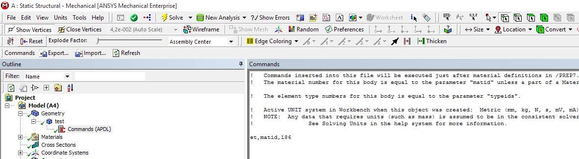
Insert a command snippet:
ET,matid, (e.g., ET,matid,186 to assign SOLI186 element) under the individual part in Geometry tree.
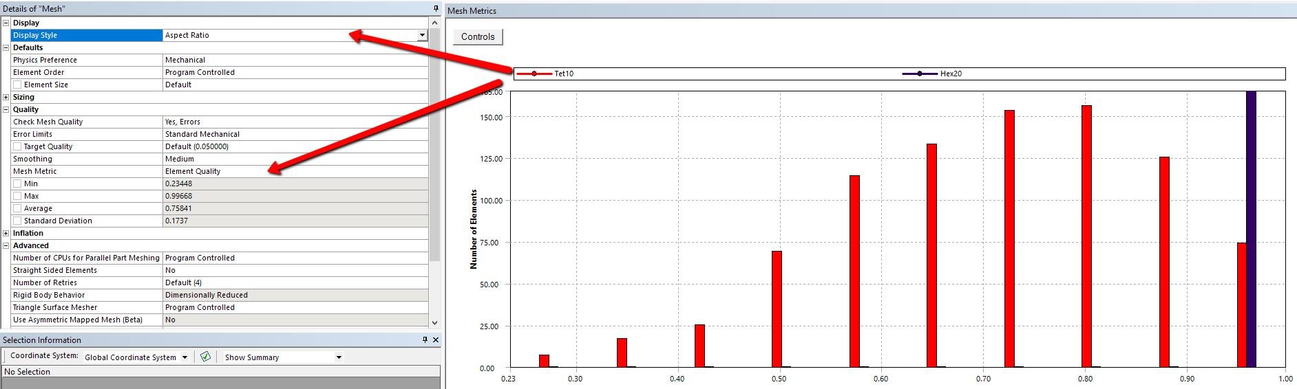
Note that the element topography must be consistent with the element shapes compatible with that element type. For instance, you cannot issue SOLID186 element to a part with midside nodes dropped (linear) elements or with all tetrahedral elements.
Â
-
August 1, 2018 at 12:07 pm
jonsys
SubscriberSandeep and Aniket,
thank you for the reply.
Is there any way to change them while using Mechanical, Workbench and not APDL?
Regards,
-
August 1, 2018 at 1:38 pm
Sandeep Medikonda
Ansys EmployeeJonsys,
Once you have created the mesh, i.e., you have chosen the meshing method, you can only change it from linear to quadratic. So let's say you have a tet mesh of your model, when you select linear you are using SOLID187 and when you are selecting quadratic you are using SOLID285.
If you want to change to a compatible element as Aniket mentions above, you would just have to place a one-line command snippet like he shows.
What is your specific case, what mesh do you have and what element type are you trying to change to?
~Sandeep
-
August 1, 2018 at 3:35 pm
-
August 3, 2018 at 9:28 am
jonsys
Subscriber -
August 3, 2018 at 10:55 am
jonsys
SubscriberIn works when I do it as Peter suggested on another post (SOLSH190), but not with the command line
Regards,
-
August 3, 2018 at 11:31 am
peteroznewman
SubscriberJon,
Check the Solution Output to see what elements are actually being used. When I last meshed the 3 panes with the Sweep, Manual Thin method, the mesher complained and did not use SOLSH190. I'm not sure why.
Regards,
-
August 3, 2018 at 12:05 pm
jonsys
SubscriberPeter,
In the example mentioned above I am doing some basic checks with a simply supported Laminated glass [Fig 1].
I applied Sweep (for 3 bodies) following your instructions, and I did as well edge sizing on the z direction (smallest dimension) of glass panes [Fig 2].
Solution Output shows that it is using SOLSH190 [Fig 3] and SURF154 which I think are elements for applying the surface load.
I will try again at the example with the mould (that I attached you on a previous post) and I will let you know it goes.
Â
Regards,
Jon
Â
-
August 3, 2018 at 12:09 pm
jonsys
SubscriberPeter,
I did not select any face for Source. Could that be the reason?
-
- The topic ‘check element type’ is closed to new replies.
-
3882
-
1414
-
1241
-
1118
-
1015
© 2025 Copyright ANSYS, Inc. All rights reserved.