-
-
June 28, 2018 at 4:58 am
Ulvi
SubscriberI am trying to analyse weld toe stress in T joint made of circular hollow section ( pipe ). 3D Model is prepared in solidworks with solid elements and sweep feature. The weld profile edges are all consistent in solidworks however when I import the model with .iges into ansys and assign share topology it breaks all boundary edges. This creates difficulties with meshing the part. Can anyone please advise on what is the solution here?Â
Both solidworks native file and .iges attached
-
June 28, 2018 at 8:41 am
Aniket
Forum ModeratorExporting CAD files to neutral file formats can lead to translational losses. Moreover, CAD software generally uses loose tolerances while creating the models as compared to the tolerances used by Mechanical. So something you see as coincident in CAD might not be actually coincident in Mechanical as you are seeing.
Solutions can be as follows:
1. Use tight tolerances in CAD. I do not know if it is possible for the specific CAD that you are using, but it is possible in some other CAD softwares
2. Use native CAD file using CAD-Workbench connection instead of using a neutral file format such as iges step or Parasolid
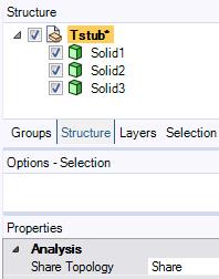
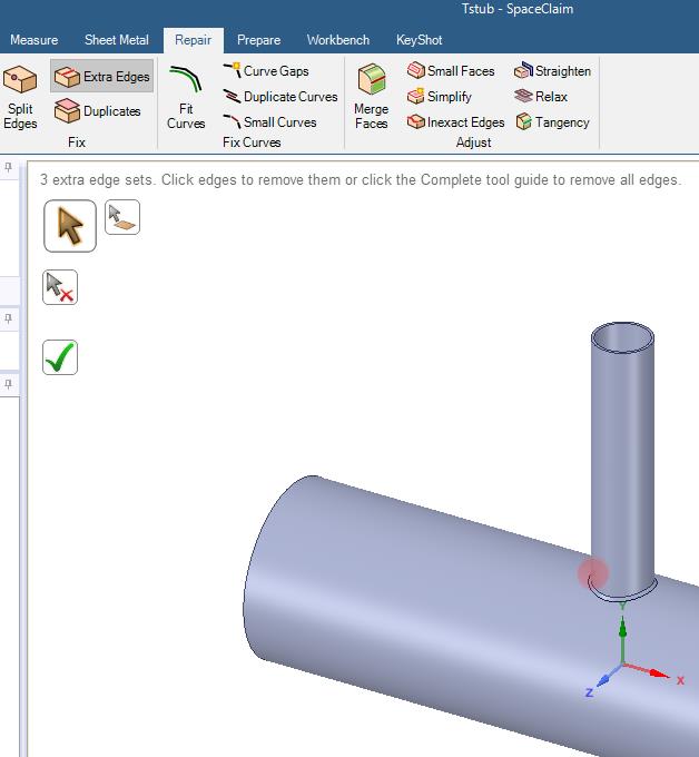
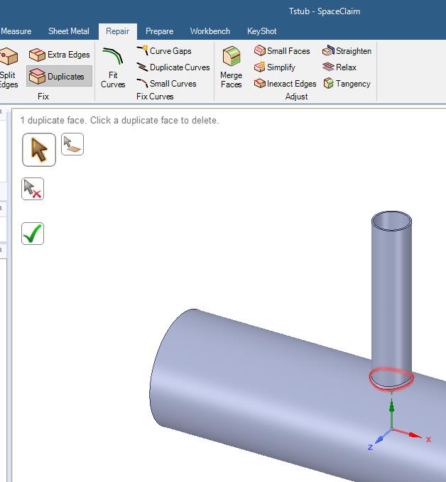
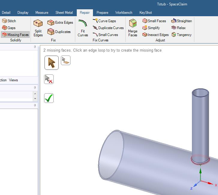
3. Use ANSYS tools such as DesignModeler or SpaceClaim to make the edges coincident
4. You can also use Mesh connections in the Mechanical to connect the mesh nodes after generating the mesh using Mesh Edit tools
Â
Â
-
June 28, 2018 at 12:27 pm
peteroznewman
SubscriberAniket's suggestion #3 was used with the SpaceClaim repair tools to repair some problems and to set Share Topology to Share.
But even after that, I did not get a good mesh. So I went back and Combined two solids, and deleted one face.
Then I finally had a good geometry for meshing.
Attached is the SpaceClaim 18.2 file.
Â
Â
-
June 29, 2018 at 8:32 am
Ulvi
SubscriberThanks for the response. I actually need those faces and splits but consistent to apply mesh controls. So I am actually looking for a solution that will not suppress any features of modelÂ
-
June 29, 2018 at 8:34 am
Ulvi
SubscriberThanks for comments. What software packages are you referring?Â
-
June 29, 2018 at 6:16 pm
peteroznewman
SubscriberThat was SpaceClaim.
-
July 7, 2018 at 6:10 pm
Ulvi
SubscriberI modelled the structure in spaceclaim too but again whereever 3 and more boundaries come together on round surface it splits edges in multiple sub-edges -
July 7, 2018 at 6:12 pm
Ulvi
SubscriberNo solution??? -
July 8, 2018 at 2:50 pm
peteroznewman
SubscriberIn SpaceClaim, I created two components, the Pipe and the Tee. The Tee has two solids, the small pipe and the weld. The Pipe has two solids, the piece below the Tee and Weld and the rest of the pipe. It looks promising in SpaceClaim...
and here is the mesh with an element size of 3 mm.
Slicing the bodies into smaller pieces may allow more hex elements in the mesh. Stay tuned.
Attached is an ANSYS 18.2 archive.
-
July 8, 2018 at 4:18 pm
-
July 9, 2018 at 11:40 am
Ulvi
SubscriberThanks Peter, Have you used chamfer option to model weld profile?
-
July 9, 2018 at 3:11 pm
peteroznewman
SubscriberNo Ulvi, I just sliced off the chamfer you provided in the solid model that you made in Solidworks.
-
July 10, 2018 at 4:36 pm
Ulvi
SubscriberThanks Peter, unfortunately I am using Ansys 17.2. Any chance that you can attach a compatible file?
-
July 10, 2018 at 8:33 pm
-
July 10, 2018 at 8:55 pm
-
- The topic ‘SolidWorks to Ansys’ is closed to new replies.
- FSAE CFD – Lesson 1 Preparation question (Using Discovery)
- Project lines/edges into a face with the direction normal to the face
- Script for subtracting models
- No preview in explorer with scdox file
- Multiple Instances of SpaceClaim taking multiple licenses
- Issues after installing new service pack 2024R1 (sp5)
- Spaceclaim file reference error
- Add-in Error Excel
- Problems with loading my Discovery Mesh into Fluent
- Missing SubDivWrapper.dll
-
3912
-
1414
-
1256
-
1118
-
1015
© 2025 Copyright ANSYS, Inc. All rights reserved.