-
-
July 16, 2023 at 5:24 am
Dhanush Kumar K K
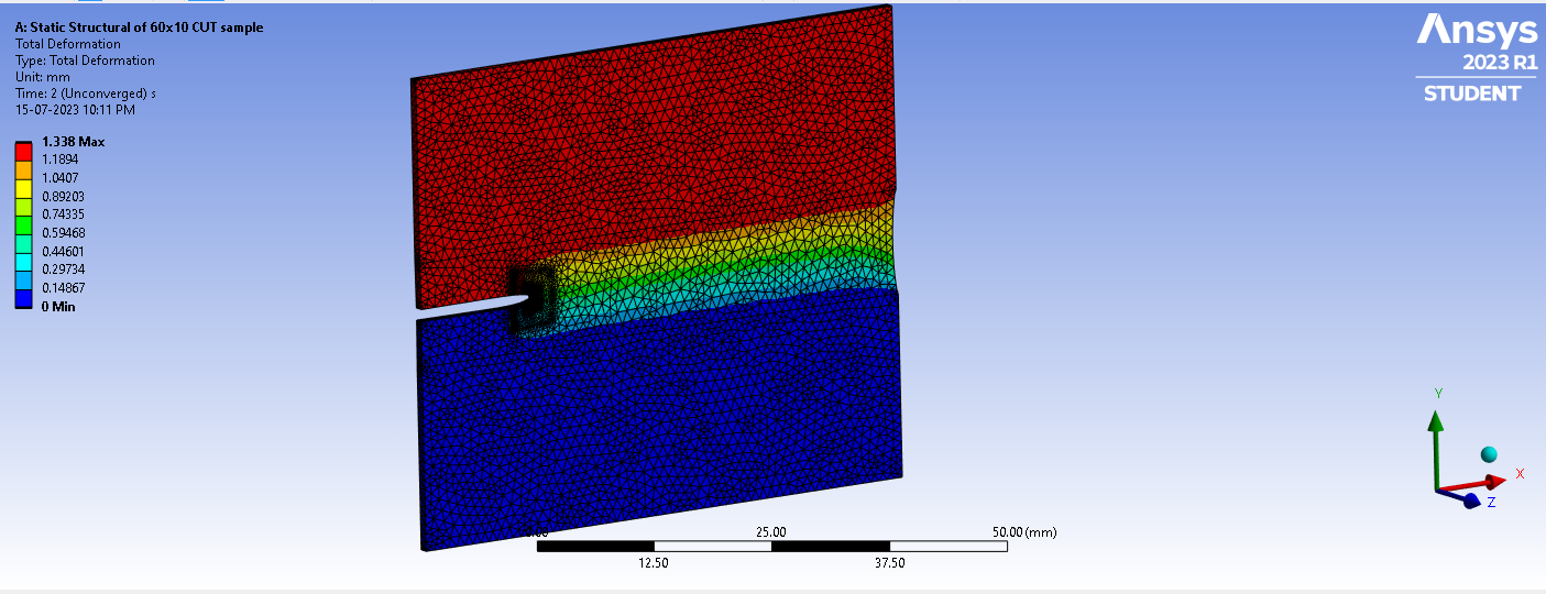
SubscriberI am doing a uniaxial tensile test of a hyperelastic sample (60mm*50mm*1mm), one with a notch and another without a notch. The uniaxial tension for a notched sample is not converging (for an un-notched sample it converged easily), I am using SOLID 285, pure tetrahedral mesh, large deformations on, quasi-static on, used steps and substeps for slow loading, fine mesh at the tip of crack & followed the videos and other suggestions by Ansys, however, I am getting high elemental distortion error.
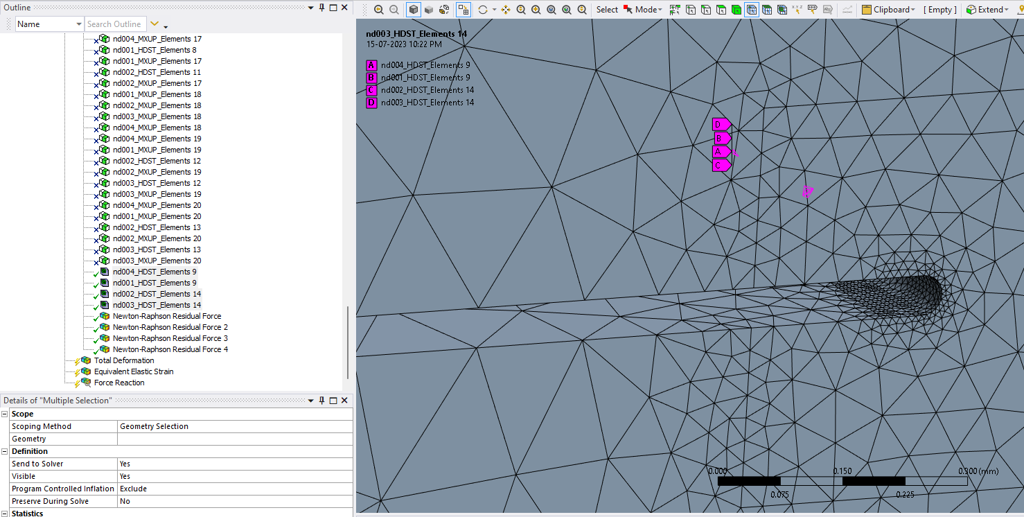
The above image shows the close-up image at the notch tip and the high distorting elements
-
July 16, 2023 at 12:41 pm
peteroznewman
SubscriberI suggest you use a Sweep Mesh Method to get linear Hex elements and put at least 8 elements through the thickness.
Insert a command object under the body to set Keyopt(6) to 1 to enable Mixed u-P element formulation and set Keyopt(2) to 1 to enable Reduced Integration.
Slicing the solid into several pieces may make it easier to get ideal element shapes but use Shared Topology to connect the mesh to avoid using Bonded Contact.
-
July 17, 2023 at 2:03 am
Dhanush Kumar K K
SubscriberFirst of all, thank you, Peter. For all your suggestions which I found very helpful in older feeds/threads.
I could make a pure hex mesh with solid 185 & further by slicing the solid. I used MultiZone as I couldn't get sweep to mesh properly. Still the solution is not converging and high distorting elements are detected.Also, after I apply the shared topology in spaceclaim/DM, the solid is not visible in mechanical, it says the updated model uses a different unit, which I checked.


-
July 17, 2023 at 10:56 am
peteroznewman
SubscriberI will take a look at your original model with a single solid. In Mechanical, clear generated data on the Mesh then File, Save then File, Archive to create a .wbpz file.
Upload that file to a Google Drive (or equivalent) so that anyone can download the file and paste the link to that file in your reply.
-
July 17, 2023 at 6:04 pm
Dhanush Kumar K K
SubscriberPlease find the link. It has two files available, one without the analysis results and the other with the results. Thank You
https://drive.google.com/drive/
-
July 18, 2023 at 1:03 am
-
July 18, 2023 at 1:37 am
Dhanush Kumar K K
SubscriberI have added the solid files, could you please check if it's now accessible. Thanks
-
July 18, 2023 at 9:02 pm
peteroznewman
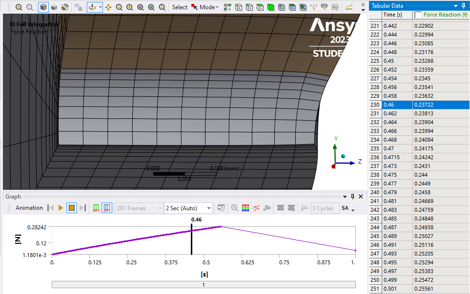
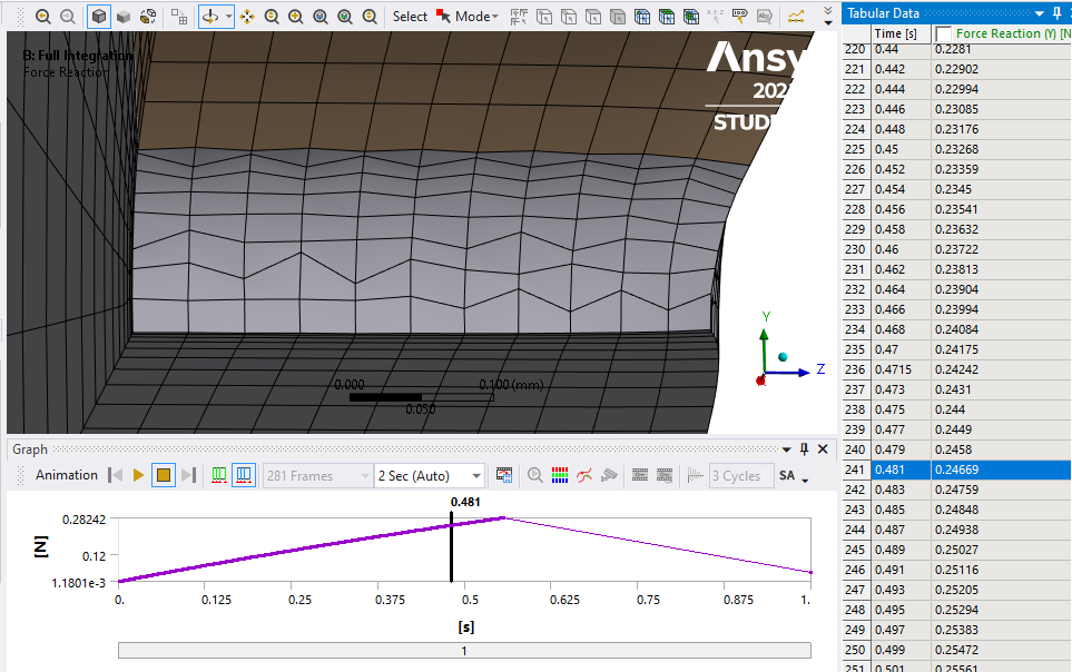
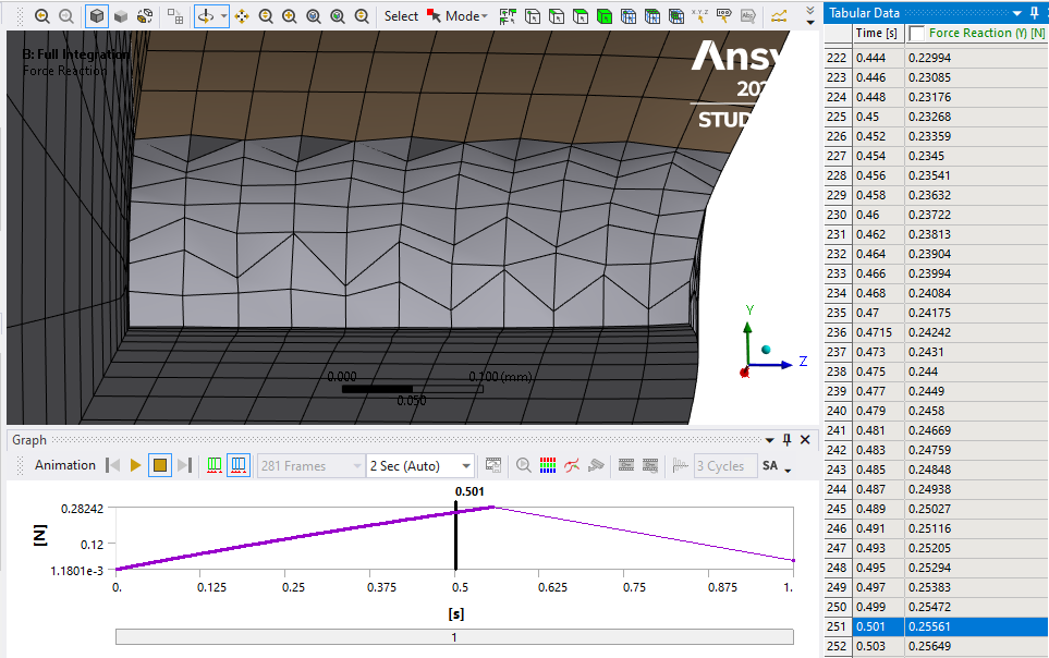
SubscriberThese are linear hex elements with Full Integration and Keyop(6)=1 for mixed u-P formulation.
Note that this is a quarter model: half the thickness with a symmetry plane at the midsurface and the top half of the sheet with a symmetry plane at the center of the notch slit. The reaction force is half that of a full model due to a model having only half the thickness.
One problem with Hex elements is they can develop an Hourglass deformation mode. The following 3 slides show it being initiated.
Here is the link to the ANSYS 2023R1 archive. https://jmp.sh/zMLYOn8J
-
July 18, 2023 at 9:46 pm
Dhanush Kumar K K
SubscriberThank you very much for the help.
I need to do the simulation of up to 10mm displacement, is there any way I can obtain convergence by using finer mesh (I now have access to a full license), or should I resolve to using a plane stress condition?
-
July 18, 2023 at 10:00 pm
peteroznewman
SubscriberThe 3D model has elements with a high aspect ratio which tends to degrade into an hourglass mode which ultimately leads to a failure to converge. I could not improve the aspect ratio within the limits of the Student license, but if you have a full license, you can improve the aspect ratio and the simulation may continue solving for a larger displacement.
-
July 19, 2023 at 1:00 am
peteroznewman
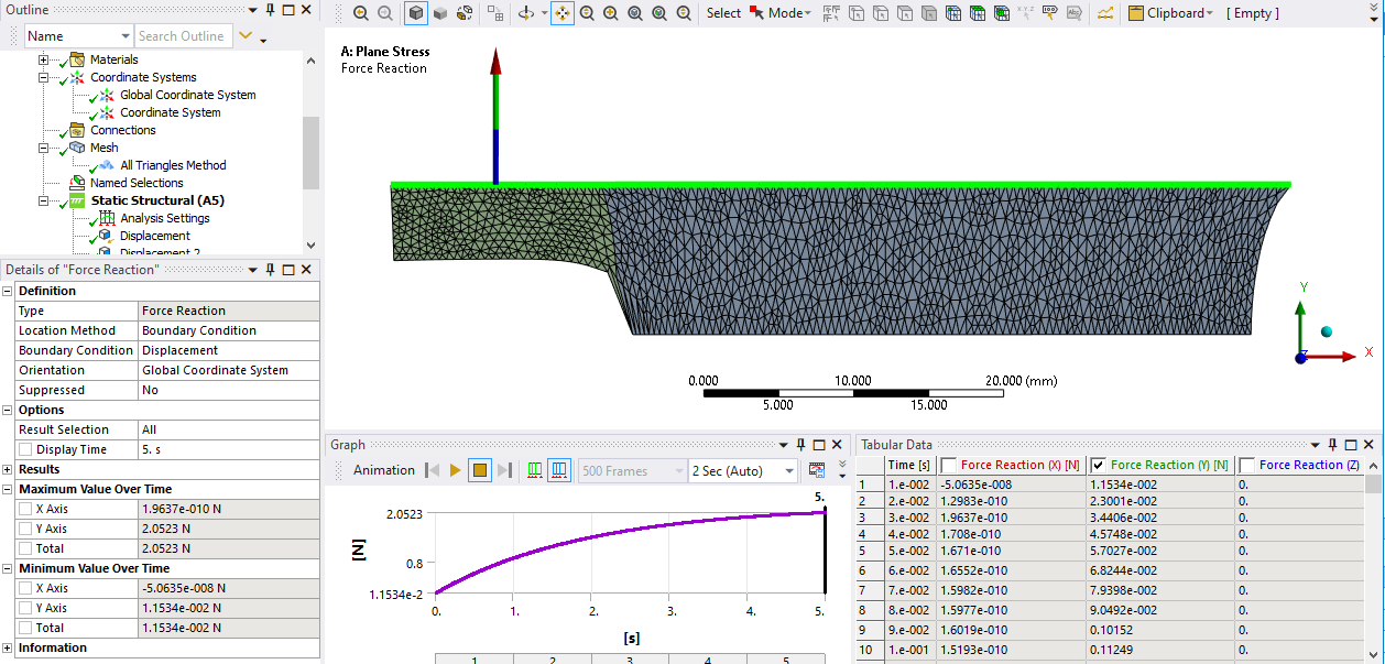
SubscriberHere is a Plane Stress solution that computes out to 10 mm displacement (5 mm on the half model). I suggest a mesh independence study be performed to see if the results change as the elements are remeshed with different sizes and element order. The mesh below used linear triangles.
Here is the project archive link: https://jmp.sh/XV68eYbU
-
July 19, 2023 at 1:50 am
Dhanush Kumar K K
SubscriberThanks again, I’ll do a study on the analysis of the different types of meshes and look at the comparison on the final displacement.
-
July 19, 2023 at 1:33 pm
-
July 19, 2023 at 1:36 pm
-
July 21, 2023 at 3:44 am
Dhanush Kumar K K
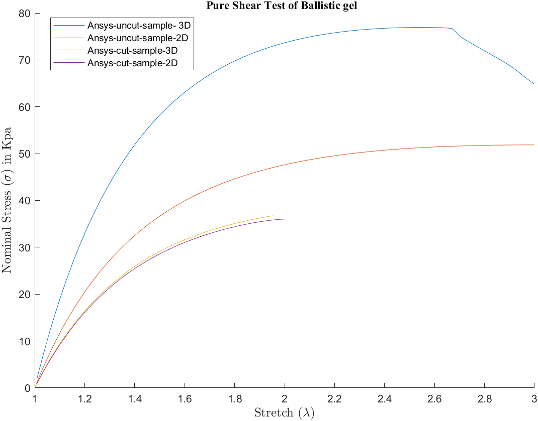
SubscriberI have a question, I am comparing the 2d and 3d simulations for the results. For the cut sample / notched sample both 2D and 3D are matching (both are full-scale models), however, with uncut/un-notched sample the 2D and 3D results are not matching.
I am using the 2D geometry in the workbench and specifying the thickness for plane stress as 1mm.
If I change thickness to 1.5 for un-notched, the results will match. I am not able to understand why the mis-match is happening between 3D and 2D plane stress models for 1mm thickness.
-
July 21, 2023 at 12:54 pm
peteroznewman
SubscriberThat is a difficult question to answer, and very difficult without looking at your models.
-
July 21, 2023 at 10:16 pm
Dhanush Kumar K K
SubscriberThe problem was that ansys was not considering the thickness for plane stress (no matter what thickness, it used to give same force results), all I had to do was delete and create a new analysis.
Also, I am looking into SOLID 185, changing the formulation of elements with hourglass control. How do I specify the HGSTF factor, is it in apdl command, also how do I decide the value for it. Thank You
-
July 22, 2023 at 11:33 am
peteroznewman
SubscriberANSYS has historically had a problem changing a 3D model into a 2D model. I have posted many times that if someone in Workbench forgot to change the Geometry cell from 3D to 2D before they opened Mechanical and started building a model, that they had to abandon the work that was done in that model and start with a fresh model.
That means starting with a new analysis system such as Static Structural and pulling the geometry into that system opening the Properties tab in Workbench and setting the Ansys Type to 2D before opening the Model cell.
You may have changed a 3D property to 2D on an existing model and suffered defects in the computation because of that. Ansys should do more to protect users from this defect.
-
-
July 21, 2023 at 11:19 pm
peteroznewman
SubscriberFrom the ANSYS Help system
HGSTF – Hourglass Stiffness Scaling factor if KEYOPT(2) = 1 (Default is 1.0; any positive number is valid. If set to 0.0, value is automatically reset to 1.0.)
I show an example of how to set a KEYOPT in my archive for the solid mesh.
This scaling factor is a REAL constant for the elements that have Keyopt(2) = 1. I expect values larger than 1.0 will have more effect on controlling hourglass modes. I’m not sure what problems will occur if too high of a value is used.
The Command object is put under the solid body in the Geometry branch of Mechanical and this is the code that goes under it:
keyop,matid,6,1
keyop,matid,2,1
r,1,2.0
The r is the REAL command and Real Constant 1 is the HGSTF and the value is 2.0
I haven’t tested this code but I will and edit this post if needed.
-
July 22, 2023 at 12:19 am
Dhanush Kumar K K
SubscriberThank you very much, Peter. ?
-
- The topic ‘Convergence Issues in Hyperelastic Material – Non linear Structural Analysis’ is closed to new replies.


-
4858
-
1587
-
1386
-
1242
-
1021

© 2026 Copyright ANSYS, Inc. All rights reserved.

