TAGGED: bolted-connection, fatigue-analysis, psd, random-vibration
-
-
July 9, 2023 at 9:31 pm
brunotav405
SubscriberHi!
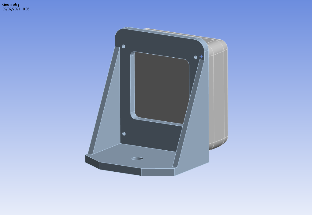
i'm trying to make an PSD analysis of the structure showed below.
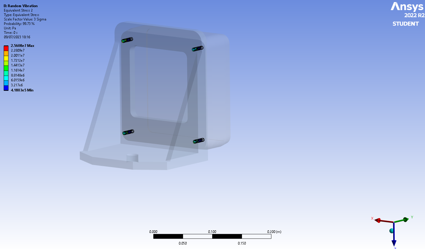
Giving more details about my model, the boundary condition is that the bigger hole is fixed. In addition, a 3 axis PSD profile is apllied in the cilyndrical surface of this bigger hole as well. The joint of two parts is modeled as 4 fixed joints beetween the 8(4+4) cylindrical surfaces. I managed to run the simulation and retrieve Von Mises stress in the holes surfaces, like I show below:

That would be enough to perform a simplified static structural analysis on the 4 M8 bolts that connect two parts. However, my main goal is to perform a fatigue analysis on the 4 bolts themselves and retrieve the number of cycles to failure. Do you guys know how to perform this kind of analysis? I was planning on using the Fatigue tool of this same Random vibration Modulus, but I'm struggling to model the bolted joint in a way it can reflect well the real behavior of my structure. I read something about moddeling bolts as line bodies and applying a pretension load, but I don't know if it works in Random vibration Analysis, so if you could help me, I would be grateful. You can assume that the bolt pretension is known and that I also have the 4 M8 bolts CAD model to work on.
Thanks. -
July 10, 2023 at 12:54 pm
Lydia
Ansys EmployeeHello,
Performing a random vibration analysis on bolts modeled as line bodies works, but it depends on your specific analysis goal. Line bodies or beam elements are highly efficient and are mainly used when the primary interest is not the stress distribution in the bolts but the overall behavior of the assembly under a certain load, including vibrational loads. They save computational time and resources, but have limitations, such as the inability to calculate shear stress and a reduced number of stress components (only 3 as opposed to 6 in 3D solids). Therefore, if the study’s objective is to assess the performance of the assembly as a whole under random vibration, using beam elements to represent the bolt could be suitable.
However, I understand that you need precise stress or strain information at the bolts during vibration, so using 3D solid elements would be recommended. Check these two courses Modeling the Bolt and Preload | Ansys Innovation Courses , Connecting Bolts with the Rest of an Assembly | Ansys Courses to understand how bolts are simulated.
Also, I think inserting the Fatigue Tool on your already extistent PSD modulus is a good idea, providing that you have modeled your bolts correctlly and you get as detailed results as you need.
Hope this helps
-
- The topic ‘Random Vibration fatigue analysis of a bolted Joint’ is closed to new replies.


-
4613
-
1530
-
1386
-
1209
-
1021

© 2025 Copyright ANSYS, Inc. All rights reserved.


