-
-
July 3, 2023 at 8:00 am
Mattias Scheffler
SubscriberHi,
I am performing a static structural crimping simulation. I am studying the gap between two objects at the end of the crimp process.
What I can do right now is to compute the gap between two contact surfaces with the contact tool (see the attached figure)
What I would like to get is the gap according to each direction (x and y axis in this case because it is an axisymmetric simulation). What are the steps to project this gap onto each axis?
Regards,
Mattias
-
July 6, 2023 at 4:25 am
mjmiddle
Ansys EmployeeI don’t see any good way to do this. Why do you need this? Do you need this to apply displacement load in a continuation analysis? Note that you can get the deformed geometry by linking solution cell to a downstream model cell to continue an analysis from the deformed geometry:
In this downstream, deformed model, you can use nodal selection filter along with “Home [ribbon] > Selection Information” to measure distances in the deformed geometry.
Or you can right click on a result in your analysis (upstream system here), and “Export > STL File” with the scale factor set to 1.0 in the Result ribbon. Then load this into SpaceClaim and you can measure distances on the mesh, or make CAD geometry over the mesh-type geometry and measure locations on the geometry. Note that if you right click on the Geometry in the Outline in the downstream system, you can export a pmdb format of the deformed geometry and load this into SpaceClaim. This loads as a mesh. Or you can load into DesignModeler, and set to DesignModeler type, rather than workbench type on the import feature to have it automatically create CAD geometry. But this works only for simple geometry. If your model is 2D, this may work easily.
-
July 6, 2023 at 5:11 am
mjmiddle
Ansys EmployeeThere is some possibility to do this with APDL, but it gets involved. You can’t get element normal at nodes for the contact elements. So you would have to look up the contact type in the APDL element reference:
https://ansyshelp.ansys.com/account/secured?returnurl=/Views/Secured/corp/v231/en/ans_elem/Hlp_E_LIBRARY.html
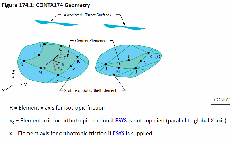
For example, if contact side is scoped to a face in a 3D analysis, this uses CONTA174:
Different scoping type (edge, vertex) and different analysis dimension (2D) will use different contact type: contact 172-178. Check the ds.dat in the solution directory to see what kind of contact element it used (ET command in the contact definition). You use UPCOORD to set nodes to deformed locations and use *GET to get the locations of the corner node of interest. Or get displacement and undeformed node locations using *GET and add instead of the UPCOORD command. Use the CONTA174 node location schematic for IJKLMNOP to get 2 adjacent midside node, and then *GET to get the locations. Compute vectors, then cross product to get normal vector. This will not be the exact normal vector at the node since contacts can have curvature, but it will be the nearest normal measured from linear assumptions to midside nodes. The *GET will be getting preprocessing values, so this works with CSYS. You can use CSYS,0 to make sure you are reporting the locations in the global coordinate system. In the CONTA174 reference, you can find the output quantities. Near the end you can find the GGAP (geometric gap) in the NMSIC table for each corner node.
You can use *GET to get the NMISC values. Assuming this value is in the direction of the normal vector you computed at the node earlier, you can then compute the projection of this value into the 3 global coordinate system axes.
Of course, your APDL code would need to loop over selected elements, and then loop over each corner node of each element to do this (in order of IJKL, so you know how each is connected to MNOP). You can use *CFOPEN to open a file for writing, and use *VWRITE to write each line. Use *CFCLOS when done. This will create a space or comma delimited file depending on what characters you insert. You can open this file in Excel. Your APDL script would also need to average midside node gap values from the corner nodes. For each midside node, you would need to compute the normal vector from 2 vectors you compute from the locations of its 2 adjacent corner nodes. Check for linear case.
-
- The topic ‘How to compute the gap between surface in each direction?’ is closed to new replies.


-
4838
-
1587
-
1386
-
1242
-
1021

© 2026 Copyright ANSYS, Inc. All rights reserved.


