-
-
June 22, 2023 at 7:09 pm
wancheng gao
SubscriberHello Community,
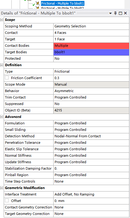
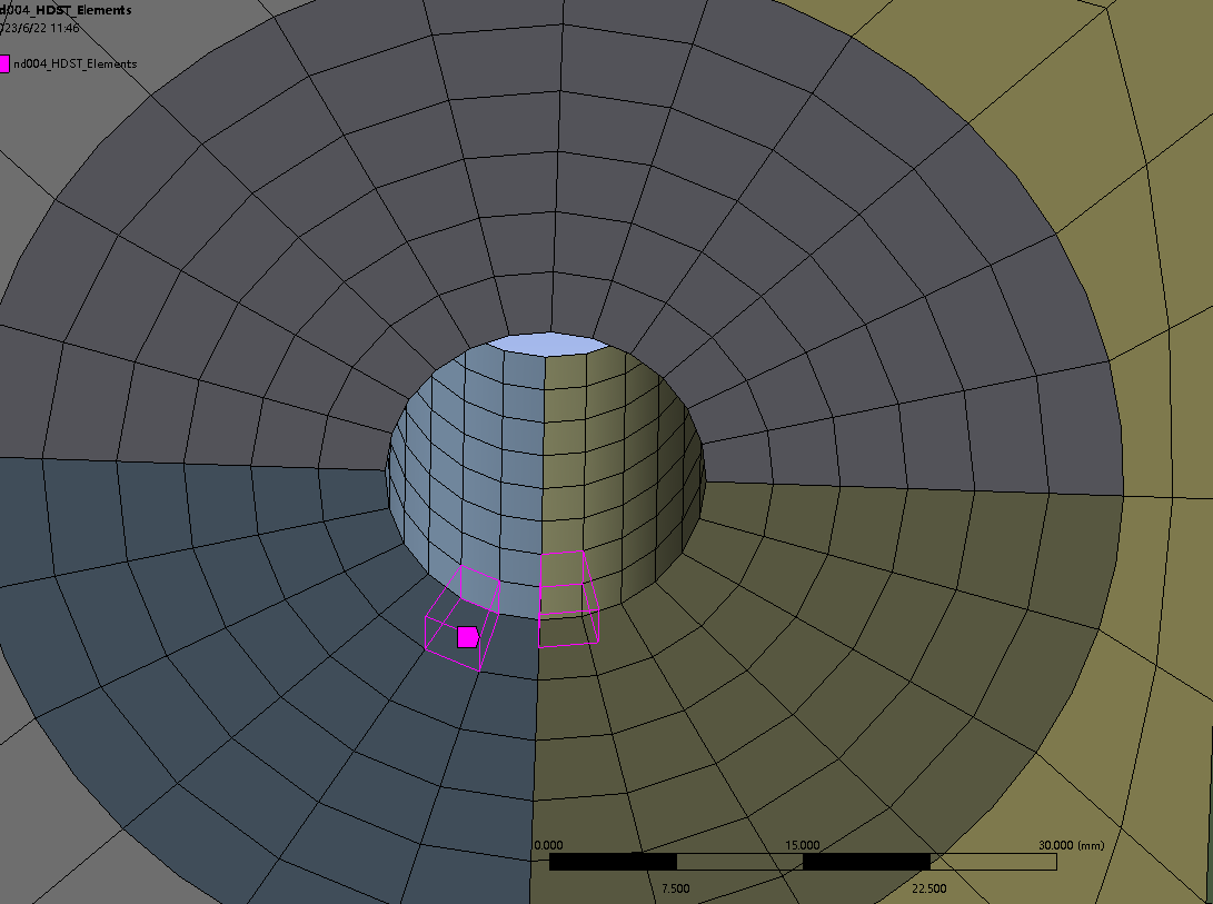
I encountered a divergence problem in modeling the cracks (Fig.1 marked in red) by defining CZM elements near bolt hole where the bolts are hidden in the figure. The elements near the bolt holes are already linear (dropping the mid node) . The bolt were created one frictional contact together with the two seperate parts of the bolt hole material with the setting in Fig.2.
Fig. 1
Fig.2
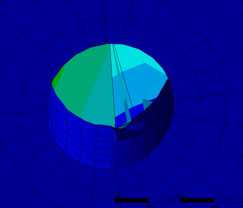
The solution output said highly distorted elements occurred and two elements are turning inside out (Fig. 3)
Fig.3
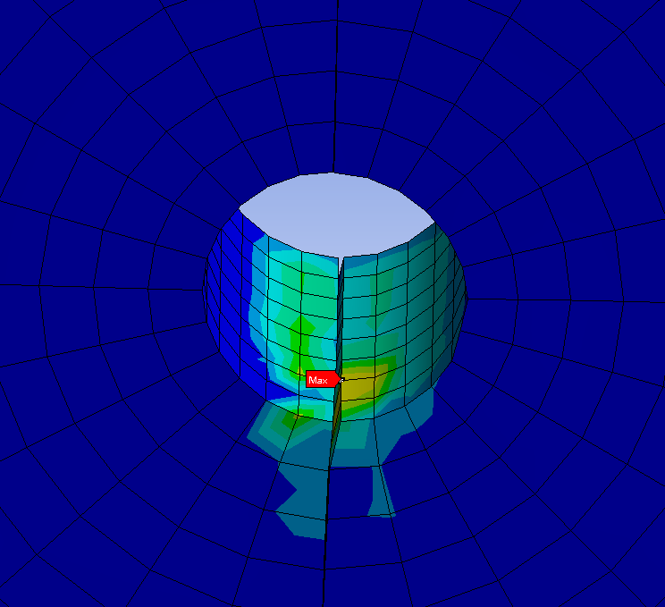
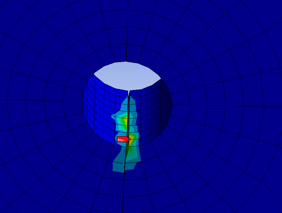
Also the newton-raphson residuals are presented at this bolt hole. The violating elements are also displayed. (Fig. 4)
Fig.4
Hopefully some experts can provide guidance on resolving this issue and helping me out!
Thank you so much!
Kind regards,
-
June 28, 2023 at 9:11 pm
John Doyle
Ansys EmployeeWhat is the expectation when this separation begins in the physical part? Could it be that the nonconvergence is indicative of a physical instability? What is the extent of the CZM separation?
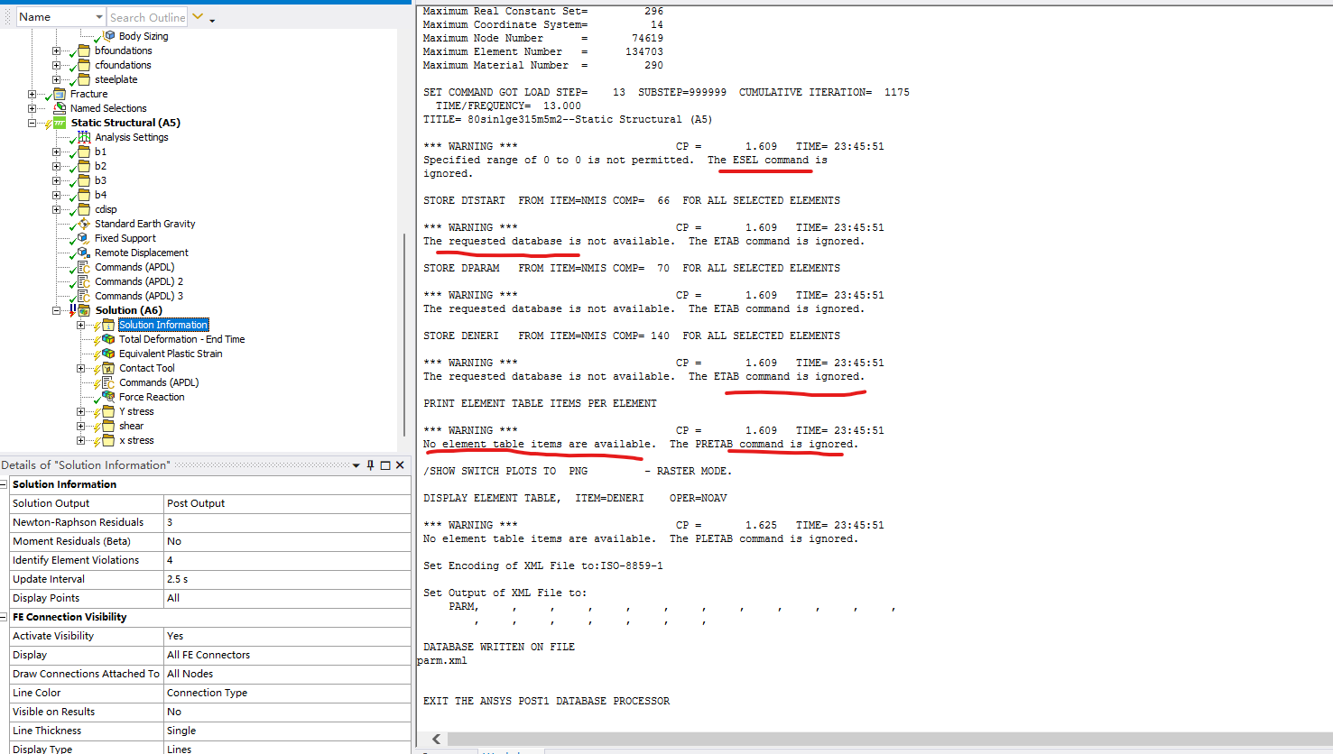
Can you postprocess the ETAB results for the CZM parameters DTSTART, DPARAM, DENERI, DEMERII and DEMER ? See Table 174. 2 of MAPDL Elements Manual and the ETABLE command docs for more details.
It is difficult to say more without seeing the whole model and all the relevant details.
-
June 29, 2023 at 12:58 pm
John Doyle
Ansys EmployeeIt might also be helpful to explore options with artifical damping added to the CZM material model. Please refer to Section 4.11.2.1 of the R2023-R1 Theory Manual for details, along with documentation on TB and TBDATA commands.
-
July 2, 2023 at 6:41 am
wancheng gao
SubscriberDear John,
Thank you very very much for your advice! Sorry for the late reply because I did not notice there was a reply to my post.
I found this sample command snippet provided by you in one of my other posts to post process the CZM debonding parameters.
***********
set,last
esel,s,type,,cid1 !select contact element type ‘cid1’
etab,dtstart,nmisc,66 !load step time during debonding
etab,dparam,nmisc,70 !debonding parameter
etab,deneri,nmisc,140 !debonding parameter
pretab,dtstart,dparam,deneri !print results to solver output
/show,png
pletab,deneri !plot critical fracture energy
***************
I am really new to APDL command and I have to humbly ask a few studpid questions if you don't mind...
1) Do I have to insert a APDL command snippet to name the czm bonded contact for which I want to investigate? I am asking because there are 18 different CZM bonded contacts in the model.
cid=czm1 ! Define the name of this CZM bonded contact is "czm1"
2) After the name of the contact is defined, I just need to change the 2nd row of the sample command to:
esel,s,type,,czm1
Is this correct?
3) I reviewed the ETABLE commands and as well as the Table 174.2 and 174.3.
I don't really understand what EIJKL means, so do I have to change the numbers 66, 70 and 140 in the command?
4) Forgive one more stupid question. The solution has already stopped. Following Question 1, I guess if I were to add a APDL command snippet under one of the czm contact to define cid name, do I have to solve it again? because it took a long time to run the model....Shall I insert this sample command snippet under "solution" or "analysis" section?
Looking forward to your guidance!
Kind regards,
-
July 2, 2023 at 6:51 am
-
-
July 4, 2023 at 3:57 pm
wancheng gao
SubscriberHello community, can anyone share some genious idea about this?
Thank you very much! ?
-
July 5, 2023 at 6:43 pm
John Doyle
Ansys EmployeeYou might need to add another command object under the contact pair in question with the command:
‘cid1=cid’
This will create a permanent parameter (cid1) for the contact element type # of interest that you will refer to later for post processing.
Also, it might be necessary to specify saving all General Miscellaneous and Contact Miscellaneous results to the rst file. (See Analysis Settings Details Window =>Output Controls…)
Also, with regards to your question about meaning of EIJKL…
E = average element results
I = ‘I’ node results
J = ’J’ node results
K = ’K’ node results
L = ’L’ node results
-
July 6, 2023 at 5:46 pm
wancheng gao
SubscriberHello John,
Thank you for your great help!
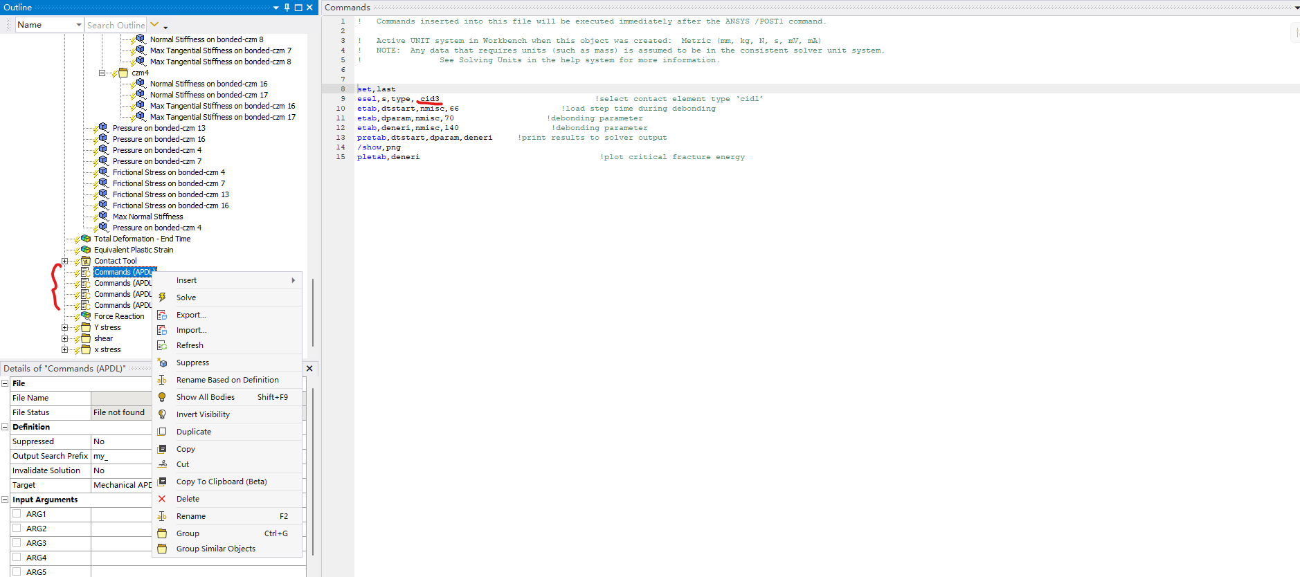
I added four command objects under the contacts of interest and name them different cid, as "cid3, cid4, cid7, cid8", respectively.
Then i found out the APDL command to output fracture energies in solution section cannot be directly excecuted. So my understanding is I must solve the model again to output the required energies, it that right? The figure of the setup is shown below.
Kind regards,
-
-
July 7, 2023 at 6:25 pm
John Doyle
Ansys EmployeeIf the results are not already saved to the rst file, then yes, you need to re-solve. If you are still having troubles, try it on a simple test model that runs fast.
-
July 7, 2023 at 10:23 pm
wancheng gao
SubscriberThank you John!
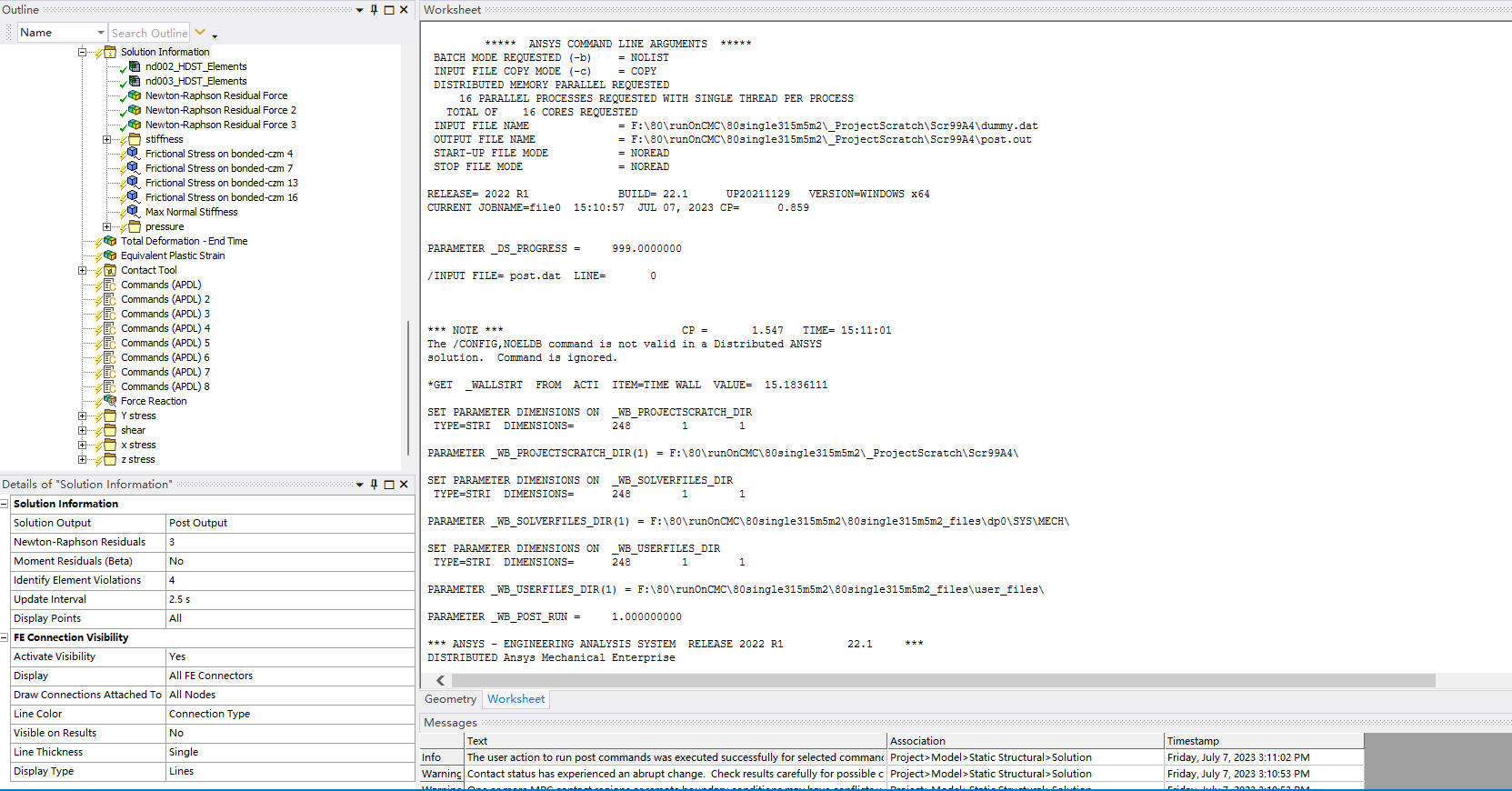
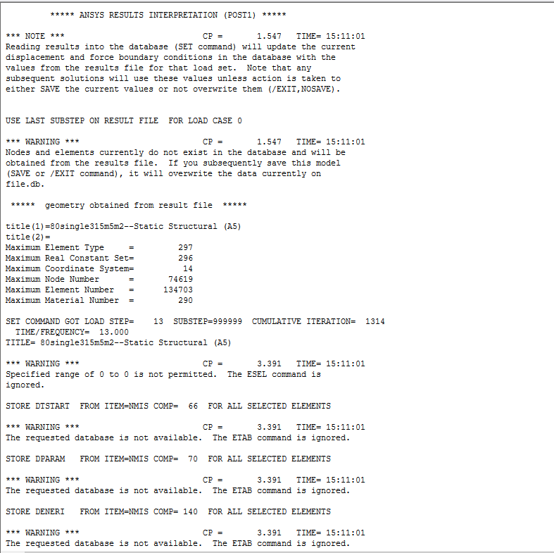
I tried following your advice and still couldn't get the energies. I inserted cid#=cid under different czm contacts of interest and inserted corresponding command snippet in solution to output the energies for each czm contact. Here shows the messages. Could you please advise me what changes to make?
Thank you!
-
-
- The topic ‘Divergent hourglassing model near bolt holes using Cohesive zone material’ is closed to new replies.


-
5074
-
1823
-
1387
-
1248
-
1021

© 2026 Copyright ANSYS, Inc. All rights reserved.


