-
-
March 29, 2018 at 3:14 pm
glopez06
SubscriberHello, I am a student at Baker College for Civil Engineering. I am working on a project for analyzing a hemispherical concrete dome under wind loading. The dome is modeled using Shell281 element and as a simple hemispherical dome of radius 12m. The wind loading is to be a velocity of 33 m/s. This project is to be done as simply as possible, without using considerations for building codes or other detailed factors. I would appreciate anyone who could explain to me a method for applying the wind load in APDL in the most simple way possible. I have very little experience with ANSYS. The attachment is the distribution of pressure coefficients that I have been working with.Thanks in advance.
-
March 30, 2018 at 3:19 pm
peteroznewman
SubscriberUsing AIM 19.0 I created this model in about 15 minutes (on my second try). It uses the Fluid-Structure Interaction workflow. There is a large block of air over a thin walled aluminum dome. The air comes in on the left face at 33 m/s.
Here is the velocity in the air
Here is the pressure on the dome
Here is the stress in the aluminum shell plotted on an extremely exaggerated deformed shape.
Many improvements in accuracy and efficiency can be made, but you can take a look at this model.
-
March 30, 2018 at 3:27 pm
glopez06
SubscriberThis is exactly what I am trying to do, but I am unfamiliar with AIM 19.0 and how it differs from APDL. Could you explain how to apply the block of air model to APDL software?
-
March 30, 2018 at 7:52 pm
peteroznewman
SubscriberI expect there is a way to map the pressure results from a Fluent model of the airflow over a rigid dome onto a Structural mesh of the dome. That is what is being done "under-the-hood" in AIM. I expect there is a manual method for APDL use. I don't know what those commands are.
I rarely use APDL code, and don't use the ANSYS "Classic" user interface, but if you want to put your input file and any other documentation in a zip file and attach it to your reply, I will play around and see what I can figure out. If you are lucky, someone else who knows how to do this will reply.
-
March 31, 2018 at 12:22 am
peteroznewman
SubscriberHere is a Fluent Model of just the air.
This is another version of the AIM model above, but with more control and only to calculate dome pressure. I am looking at how to export this data to apply to a Structural model. This page looks relevant.
There is something called a Y+ wall calculation, which estimates what the thickness of the first layer of cells over the dome should be to properly capture the development of a boundary layer in the turbulent flow. Using the 33 m/s velocity and the 24 m dome diameter, it calculates a first layer thickness of 0.014 mm. Is this necessary? When I meshed with this, I got reversed flow at the outlet, which I think means I need to increase the downstream length to the outlet. I hope one of the CFD gurus on the site will comment whether this is an adequate model of the airflow over the dome.
-
March 31, 2018 at 3:40 pm
glopez06
SubscriberThank you for your help, I was using a thickness of 0.10 m for the dome. Your AIM model seems to do exactly what I am trying to do in APDL. I have very little experience with ANSYS though, I'm sure there is a method for applying a wind load to a structure but I haven't been able to find any documents that describe that process.
-
March 31, 2018 at 5:18 pm
peteroznewman
SubscriberThis page looks relevant.
You can download a free Student license for AIM or ANSYS 19.0 then you could do the analysis in AIM or Workbench.
What version of ANSYS are you using? Is it the Student license or a Research license?
Why do you have to do the analysis in APDL software?
-
April 1, 2018 at 10:49 pm
peteroznewman
SubscriberI wanted to reproduce the AIM model in Workbench. This first video is Geometry creation and Meshing.
https://youtu.be/rFSAmt0EJTo
This second video is building the Fluent model and solving. I welcome any comments from experienced CFD members.
https://youtu.be/tmsIIte-cRg
The third video is building the Structural model and transferring the pressure load.
https://youtu.be/iGA_Fa46mEk
-
April 3, 2018 at 2:40 pm
glopez06
SubscriberI believe I am using ANSYS 18.2, and I have to use APDL because that is what my professor is requiring for this project. It is a student license.
-
April 3, 2018 at 3:04 pm
peteroznewman
SubscriberPlease put your APDL input file and any other documentation in a zip file and attach it to your reply if you want more help on this project.
-
April 5, 2018 at 3:49 pm
glopez06
SubscriberI have decided to try follow your video tutorials for doing this problem in workbench, I have never used workbench before and in your first video you say that you have started a fluent model and started a space claim to save time, could you explain how you started those things?
-
April 5, 2018 at 5:49 pm
peteroznewman
SubscriberGlad to hear you will give Workbench a try!
In Workbench, you drag the Fluent system out of the toolbox and drop it on the Project Schematic area. The Fluent system has a cell for Geometry. When you double click on that cell, it takes a couple of minutes for the SpaceClaim window to open before you can draw anything. I double clicked that before I started recording the video so you didn't have to wait those 2 minutes.
Similarly when you double click the Setup cell, it takes a couple of minutes for the Fluent window to open, and I opened that before I started recording to save time.
-
April 6, 2018 at 2:34 pm
glopez06
SubscriberI have completed all of your tutorials and followed every move that you did, my final pressure load looks like this though. I see that the values are different than the ones in your video, I'm guessing variation might be due to different versions of Ansys? but why does the image look like this? Did I make a mistake or is there a setting I need to change to have it show the color distribution better? I followed every move your made exactly
-
April 6, 2018 at 2:45 pm
-
April 6, 2018 at 3:02 pm
glopez06
SubscriberAlso, is there a way in Workbench to plot the crack patterns of the concrete?
-
April 7, 2018 at 3:05 pm
peteroznewman
SubscriberI learned how to plot cracks in Workbench using an APDL command snippet from Nayef.
Here is that code for copy paste:
/SHOW,png
/ANG,1,
/VIEW,1,0,0,0
SET,1,1
/DEVICE,VECTOR,ON
!PLNSOL,s,eqv
!SET,Lstep,1
SET,Last
PLCRACK
There is also a command snippet above that may be required. It has this code in it:
outres,all,all
You also have to have a command snippet to set the element to solid65 and the material to concrete.
Here is that code:
et,matid,solid65
MP,Ex,matid,1500
MP,Prxy,matid,0.2
MP,Dens,matid,2400e-9
TB,concr,matid
tbdata,1,0.3,1,0.304,4.278
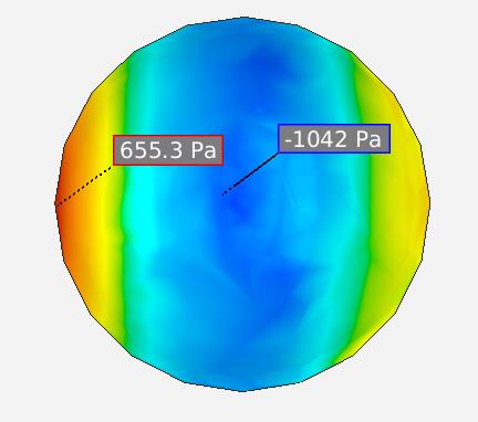
When you click on Plot, this is what you see:
ANSYS 18.2 archive is attached.
-
- The topic ‘Wind Loading on Hemispherical Dome’ is closed to new replies.
- At least one body has been found to have only 1 element in at least 2 directions
- Script Error Code:800a000d
- Element has excessive thickness change, distortion, is turning inside out
- Elastic limit load, Elastic-plastic limit load
- Image to file in Mechanical is bugged and does not show text
- Help to do quasistatic analysis in static structural module
-
1937
-
839
-
599
-
591
-
366
© 2025 Copyright ANSYS, Inc. All rights reserved.