TAGGED: psd, random-vibration
-
-
June 14, 2023 at 8:55 pm
Danial Hakim
SubscriberI would like to ask about random vibration in Ansys Mechanical. For an example of an airplane wing in random analysis, what does the response PSD obtained represent? And how to determine the PSD base excitation input (Acceleration, Velocity, Displacement)? Thank you.
-
June 15, 2023 at 1:53 am
peteroznewman
SubscriberThe PSD input for base excitation is either provided as part of a specification, or can be experimentally measured with an accelerometer connected to a data acquisition system.
The response PSD represents the data that would be recorded if an accelerometer was located at that point on the structure.
Take the free course on Random Vibration.
-
June 15, 2023 at 8:27 am
Danial Hakim
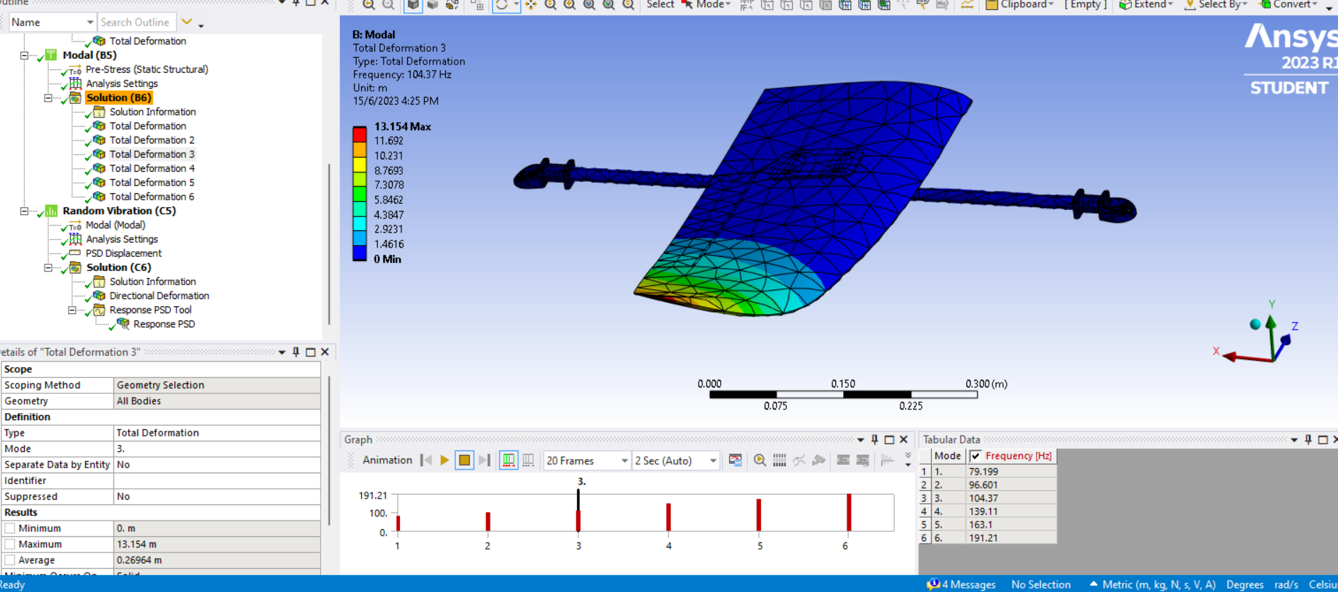
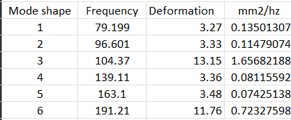
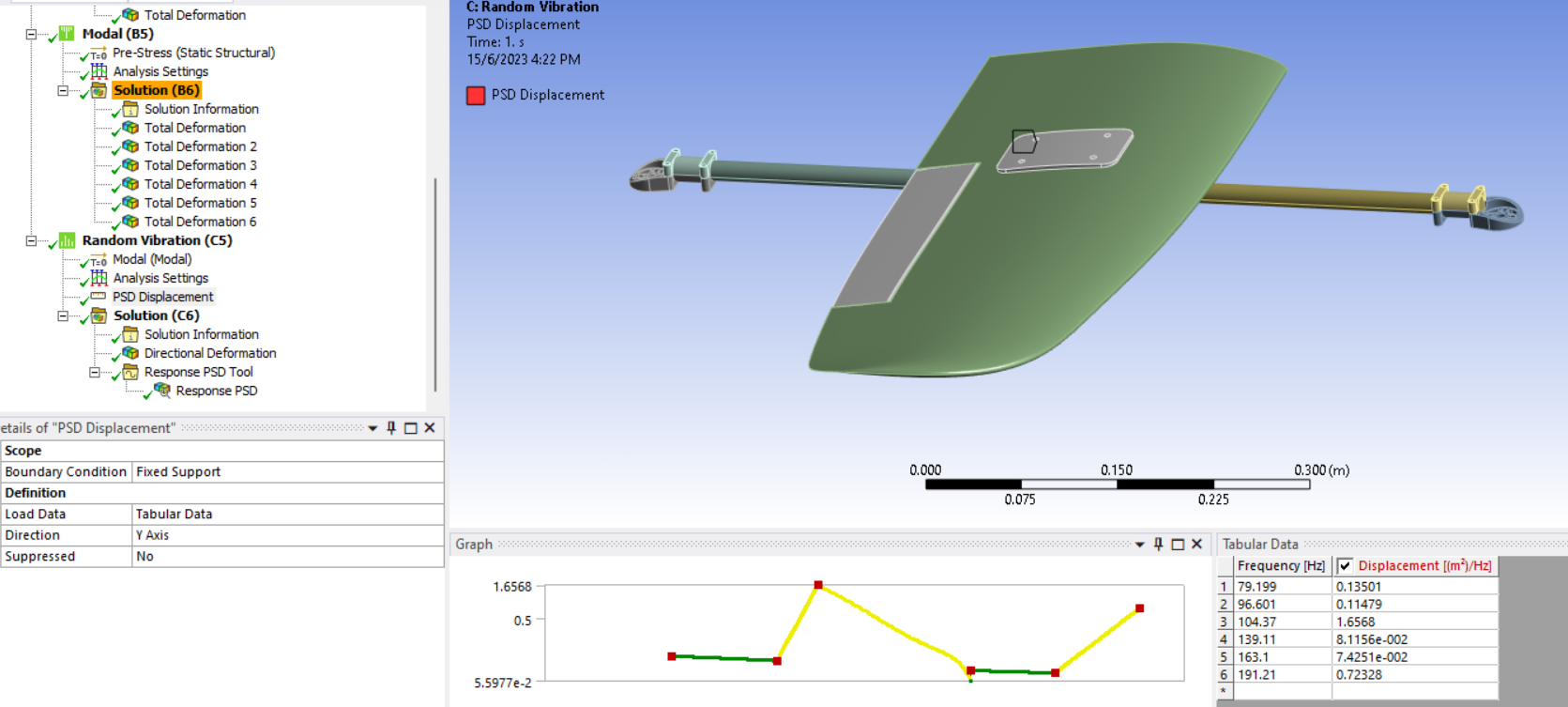
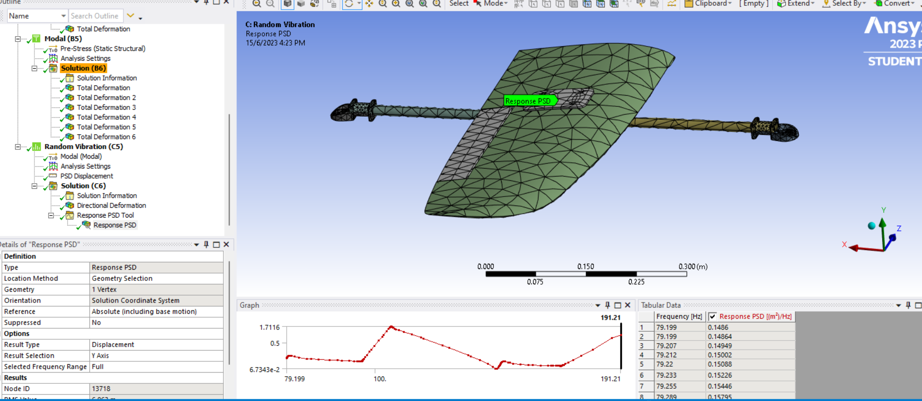
SubscriberFor my case, there are no PSD input base excitation provided and I do not have access to an accelerometer. I've tried using the max deformation from each node of total deformation in Modal Analysis to determine the PSD Displacement (m2/Hz) for Random Analysis. I used the formula (deformation x deformation) / frequency. My goal is to determine the amount of vibration exerted on the wing of the model. Does the Response PSD obtained valid? Do you have any suggestion?
Below are how I've done my analysis on the aircraft model wing geometry.
-
-
June 15, 2023 at 10:57 am
peteroznewman
Subscriber"I've tried using the max deformation from each node of total deformation in Modal Analysis to determine the PSD Displacement (m2/Hz) for Random Analysis."
Do not do that! The deformation in Modal analysis is arbitrary because there is no load in Modal analysis to create any deformation. Take the free course on Modal Analysis.
-
June 15, 2023 at 12:42 pm
Danial Hakim
SubscriberI've took the Ansys free course on Modal Analysis and Random Vibration. However, there were no mentions on how to obtain the PSD input for base excitation as in the free course, the PSD input was already given as PSD G Acceleration. Is there any way for me to perform Random Analysis on the wing structure when there are no PSD input and accelerometer provided? Thank you.
-
June 26, 2023 at 9:04 am
BALA
SubscriberNo, without PSD input it is not possible and perfroming the CFD simulation to get those will be cumbersome. You need to find the standard document which describes the perticular random vibration specifications for designing the Aircraft wing.
-
-
-
June 15, 2023 at 1:11 pm
peteroznewman
SubscriberOne source of vibration for an aircraft is the turbulent air it passes through.
An elaborate Fluid Dynamics simulation could create flutter vibrations in the wings.
-
June 15, 2023 at 2:23 pm
Danial Hakim
SubscriberHow do you reckon the supposed input PSD for an UAV model wing (whether displacement, velocity, or acceleration) ?
The previous method I used was referring from this tutorial video on YouTube (link below). Is it not valid?
https://youtu.be/h1dJsOHKE7o
-
-
June 16, 2023 at 1:35 am
peteroznewman
SubscriberI suggest you ask in the Fluid Dynamics forum about wing flutter vibrations.
-
June 26, 2023 at 11:20 pm
peteroznewman
SubscriberThe method shown in the video is not a valid method of creating an input PSD that has any relationship to any measured vibration. Input PSD tables are derived from measurements made with sensors that can detect vibration, such as accelerometers. When many measurements are made, the PSD of a large number of measurements can be enveloped to create a standard PSD table that you might see in a specification for a product. For example, the vibration a product may experience if it was bolted to a truck driving on roads, or a type of aircraft that goes through a range of conditions including take-off and landing.
-
- The topic ‘ANSYS Random Vibration’ is closed to new replies.


-
4633
-
1540
-
1386
-
1225
-
1021

© 2025 Copyright ANSYS, Inc. All rights reserved.


