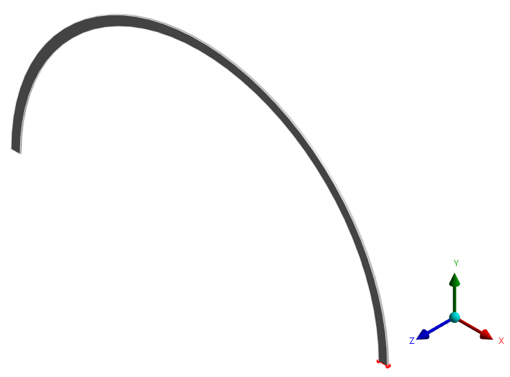
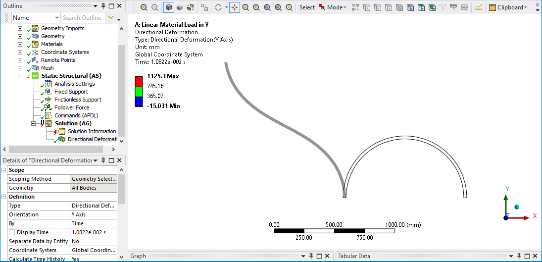
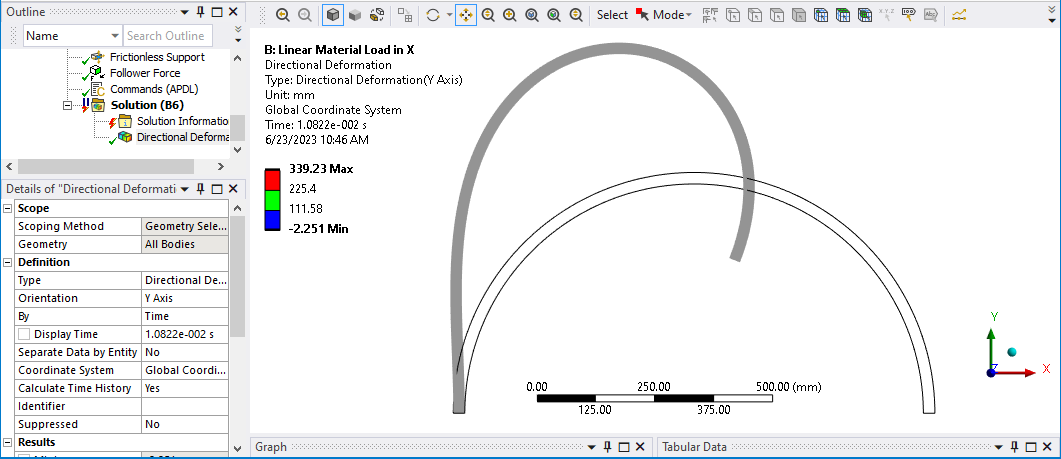
-
-
June 10, 2023 at 2:06 pm
freud farid
Subscribermy problem is a cantilever curved beam under follower load (as mention in the image )
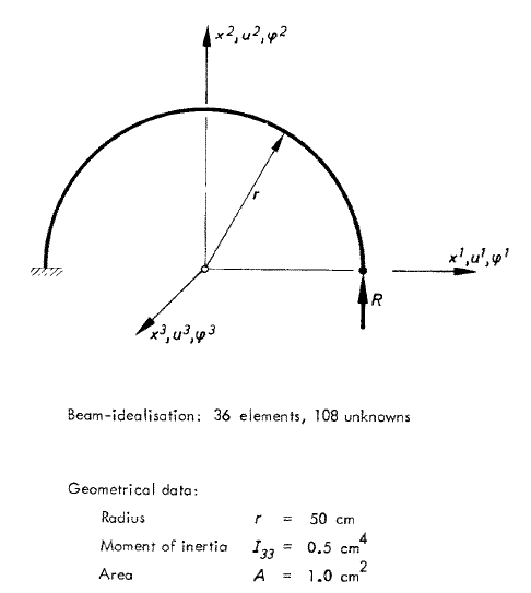
i follow all steps to apply a follower load but without result
i create a new coordinate system and use it to create a remote point on the second free end of the curved beam
then i linstall an extension named 'follower load ' and use it
always give me this error message
"The solver engine was unable to converge on a solution for the nonlinear problem as constrained. Please see the Troubleshooting section of the Help System for more information."
"The unconverged solution (identified as Substep 999999) is output for analysis debug purposes. Results at this time should not be used for any other purpose. -
June 10, 2023 at 9:21 pm
peteroznewman
SubscriberFrom your original discussion, I created a model using Beam elements. Here is the link to that model. You should use Beam elements.
The image you show above will be meshed with solid elements which are not recommended for this type of problem.
-
June 11, 2023 at 9:48 pm
freud farid
Subscriberthank you very much peteroznewman
it's very useful and give acceptable result
i have some question about the project1- when i change the material to a hyperelastic it give error , i know that the geometry is line and l must to convert it ot area or solid in order to work with hyperelastic material
how i can convert the geometry to solid without creat geometry from the begining
2- when i change the direction of applied the load (from y to x ) or the apply a moment it give error ? where is the problem
3- how i can extract the nodal coordinate of the deformed shape , i mean that (x,y) coordinate of the nodes in the deformation configuration
thank you again
-
-
June 12, 2023 at 12:52 am
peteroznewman
Subscriber- The Mooney-Rivlin Hyperelastic material model supports Beam elements, you don’t need a solid body and solid elements. You may not have created the hyperelastic material correctly. What is the error?
- When you change the load direction, what is the error?
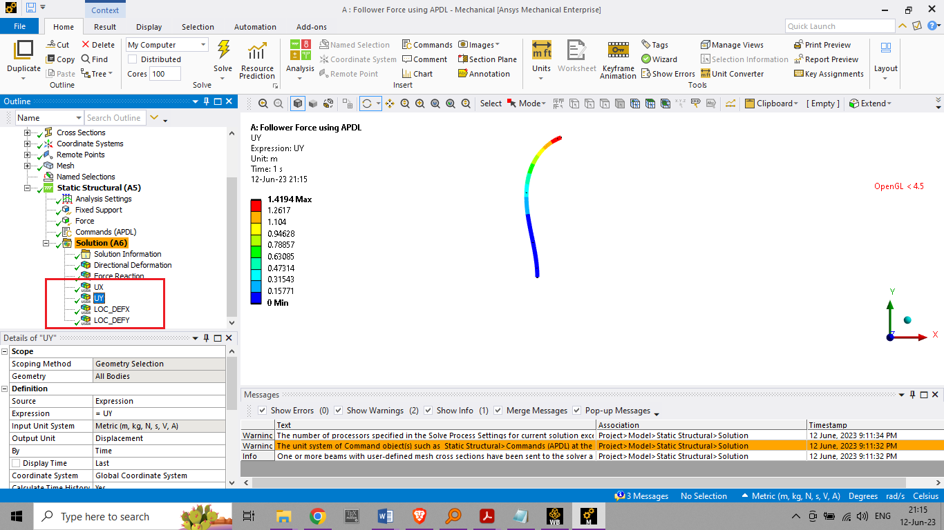
- Create a Directional Deformation for the X axis and a second Directional Deformation for the Y axis. Export the nodal deformations for these two axes. You also need the initial X,Y coordinates of all the nodes. The final X, Y coordinates of each node is the initial X, Y coordinate of the node plus the X and Y directional deformation added to the initial nodal coordinates.
-
June 12, 2023 at 9:23 am
freud farid
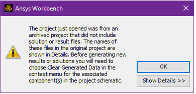
Subscriberwhen i open the file this warning appear
the error message when i change the material to mooney rivlin
"An unknown error occurred during solution. Check the Solver Output on the Solution Information object for possible causes."
another error message appear
"The unit system of Command object(s) such as Static Structural>Commands (APDL) at the time of creation, differs from the solver unit system. Check your data and results accordingly."
-
June 12, 2023 at 3:18 pm
peteroznewman
SubscriberYou have two warnings and one error. The first warning, just follow the instructions provided.
The error is because you don't have the mooney rivlin material model properly defined. You may find evidence of this in the Solution Output.
The last warning is because you have an APDL command and you are not solving in the same units as were used when the APDL command was inserted. This is a problem when you have numbers in the APDL command that need to change when the units change such as a spring stiffness. This warning is not a problem when all the numbers in the APDL command are dimensionless, such as Keyops.
-
June 12, 2023 at 6:27 pm
freud farid
Subscriberi try all the hyperelastic material but alwaus give errorr
but when i try another elastic material it work ?
i think the problem is in the element choice !?
can you explain more this point ,
- Create a Directional Deformation for the X axis and a second Directional Deformation for the Y axis. Export the nodal deformations for these two axes. You also need the initial X,Y coordinates of all the nodes. The final X, Y coordinates of each node is the initial X, Y coordinate of the node plus the X and Y directional deformation added to the initial nodal coordinates.
please can you make video like tutorial and explain how to create the example
-
-
June 12, 2023 at 7:19 pm
peteroznewman
SubscriberCreate a solid model of a straight cantilever beam, meshed with solid elements and assign the hyperelastic material, do you get the same error? If so, you have not correctly defined the hyperelastic material model.
I will see if I can find some time to explain more on the point of exporting two directional deformations and adding them to the nodal coordinates, but I have limited time. Have you tried exporting a directional deformation?
-
June 12, 2023 at 8:19 pm
-
-
June 13, 2023 at 9:59 am
peteroznewman
SubscriberRead this discussion, it tells you what to do.
Where it says to export to text file, right click on the result and the popup menu has Export on it.
-
June 13, 2023 at 10:49 pm
freud farid
Subscriberit's not work but thank you
i have more 02 question
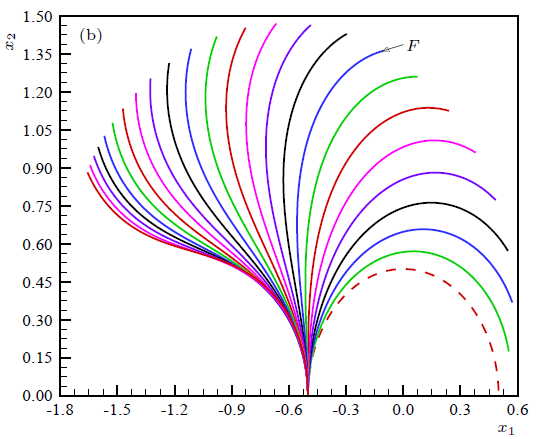
the photo bellow is the history of deformation in 24 equal load step imlemented in matlab
can e create like this in ansys ?
2- when i try to change the direction of apploed force from y to x direction , it give error
please can you try it , if it work or not
-
-
June 13, 2023 at 11:31 pm
peteroznewman
SubscriberAnsys can create all the data needed to make the plot shown in matlab by implementing 24 equal load steps and exporting the data from each load step. It would be a bit tedious to do that manually. If you want to learn to code, I expect you can automate the process of extracting the data with a script.
The matlab example shows a force that is tangent to the tip, which would be vertical at the start of the simulation. You are showing a horizontal force. Are you trying to get the matlab plot with a horizontal force? That is not the same problem.
-
June 14, 2023 at 10:21 am
freud farid
Subscriberthe first photo is the matlab plot of the vertical force load (y direction ) , i ask if can we plot the same figure with ansys ?
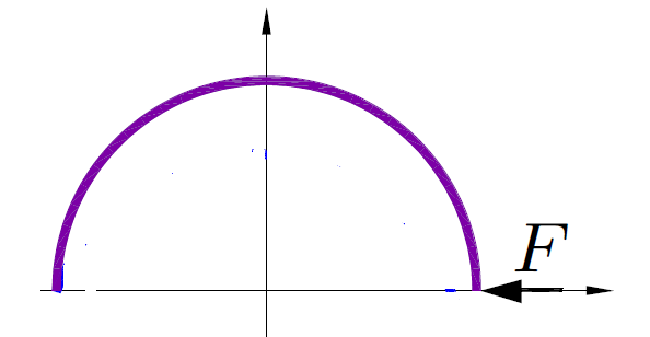
the second photo for another example with a force in x direction , i try to change the direction of the force but it give an error , i ask if you can do it with x force direction and show me the result ?
-
June 15, 2023 at 10:31 am
freud farid
Subscriberhi
please check this project
https://www.dropbox.com/s/e505q4cycjc5upj/hyper_follower_load.wbpz?dl=0
i use a newhookean hyperelastic material , the geometry is solid instead line
i apply the follower load but not converge ? please check it and fixed it ?
-
-
June 15, 2023 at 10:50 am
peteroznewman
SubscriberAnsys can't plot a figure like that. Ansys can provide all the data needed to plot a figure like that in a program that is good at plotting such as Excel or Matlab.
You put this file: hyper_follower_load.wbpj in dropbox. That file is useless without the hyper_follower_load_files folder. Open the file in Workbench and use File Archive to create a hyper_follower_load.wbpz file instead, which contains all the files needed for me to open.
-
June 15, 2023 at 12:51 pm
-
June 16, 2023 at 6:40 pm
freud farid
Subscriberhi peter any new ?
-
-
June 17, 2023 at 2:26 pm
peteroznewman
SubscriberHi Freud,
Your beam is very thin in the plane of the arc, but thick in the radial direction. That means when you apply a force in the -X direction, the beam will buckle. Buckling is a difficult behavior to capture in a Static Structural model. It is very difficult to capture when the load is a force and it is much easier to capture when the load is a displacement.
If you change the profile of your beam so it is thick in the plane of the arc and thin in the radial direction, then the part will not buckle and you may find it much easier to converge.
-
June 17, 2023 at 6:44 pm
freud farid
Subscriberplease contact me
freud1889@yahoo.com
-
-
June 18, 2023 at 2:43 am
peteroznewman
SubscriberHow will that help?
-
June 18, 2023 at 8:36 am
-
-
June 19, 2023 at 3:08 am
peteroznewman
SubscriberThe buckling problem is the same whether you push in the X or the Y direction. The arc will buckle out of plane at a very low force. I created a linear material to run two Eigenvalue Buckling analyses to find out the Load multiplier for X or Y direction loads when the upstream Static Structural model has a 0.0001 N unit load. The load multiplier is 0.997 for a load in the Y direction and 0.852 or a load in the X direction.
-
June 22, 2023 at 9:37 pm
freud farid
Subscriberthank you any way , but not helped and not give the correct results
-
-
June 23, 2023 at 12:35 am
-
- The topic ‘fellower load problem’ is closed to new replies.


-
4613
-
1520
-
1386
-
1209
-
1021

© 2025 Copyright ANSYS, Inc. All rights reserved.

