TAGGED: ansys-ls-dyna, shear-stress, simulation-crash
-
-
June 8, 2023 at 12:30 pm
Noah
SubscriberHello,
I have a question/problem with a crash simulation of a simple pipe.
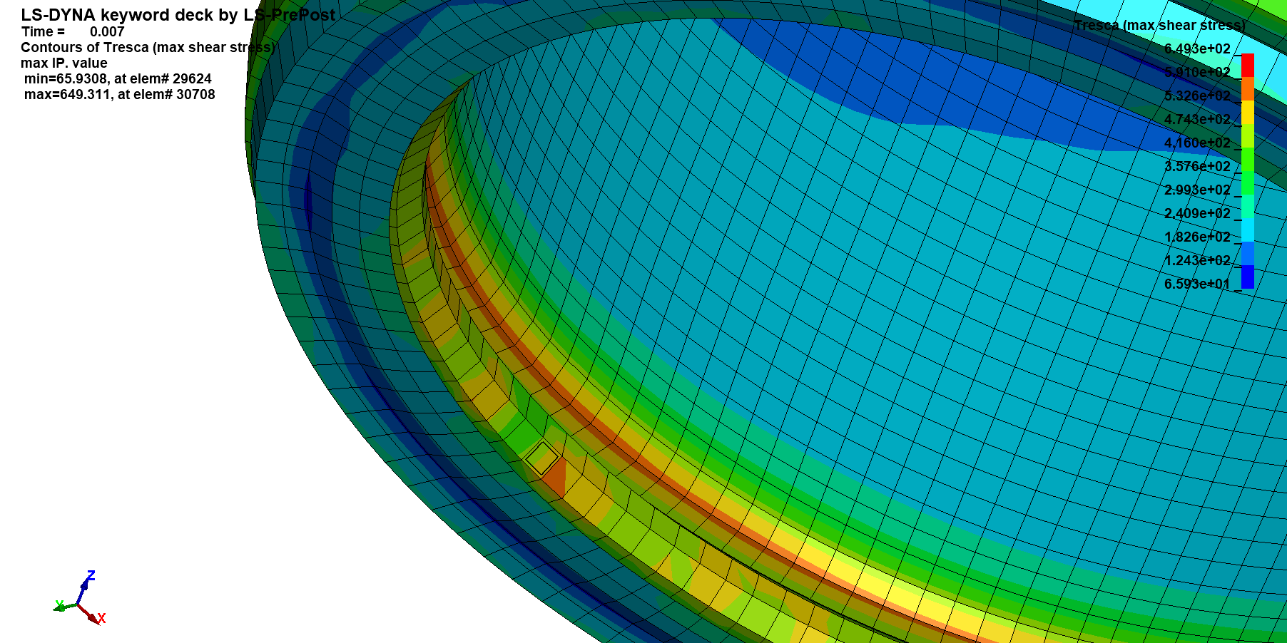
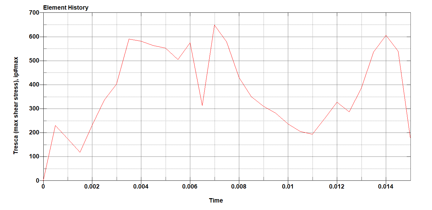
After a certain moment of deformation the following message appears:
Element deleted due to maximum shear  6.40633E+02 >  tauc= 6.37500E+02
However, the program runs through without errors until the end.
When I then look at the result in the PrePost, however, no deleted elements are visible.
This only occurs with finer meshing; this error does not occur with coarser meshing.
What could be the reason for this?
Thanks a lot!
-
June 9, 2023 at 4:56 pm
Jim Day
Ansys EmployeeGenerally, the element ID would be given in the failure message. View that element by itself when postprocessing d3plot to confirm whether or not that element is actually removed from the display the the reported time of failure. I would also plot a time history of stress for the element to see what happens to stress at the time of reported failure. If you have any follow-up to this reply, please state what element formulation and what material model are used for the failed element(s). -
June 21, 2023 at 11:58 am
Noah
SubscriberThank you very much for your answer.
I use shell elements with the formulation ELFORM 16.
Thereby I use a SHELL NIP of 3.
As material model I use MAT_107 with the appropriate error parameters of Cockcroft-Latham.
Can it be that only the outer elements that are created based on the NIP command are deleted and not the nodes? -
June 21, 2023 at 3:23 pm
Jim Day
Ansys EmployeeTo what are you referring when you say "outer elements that are created based on the NIP command"? NIP is the number of through-thickness integration points for each shell element. When an element is deleted, any nodes that are freed up will generally remain in the simulation as unattached nodes. Those unattached, free nodes will no longer participate in the contact unless the variable ENMASS in *CONTROL_CONTACT is invoked. See description of ENMASS in the User's Manual. -
June 22, 2023 at 9:40 am
Noah
SubscriberThat was my wrong interpretation.
Attached is a picture of an element that exceeds the shear stress but is not deleted.
Also note the diagram where the element exceeds the maximum shear stress of 637.5 MPa.
What could be the reason for this?LS-DYNA keyword deck by LS-PrePost
*CONTROL_BULK_VISCOSITY
$#    q1     q2    type   btype   tstype   Â
    1.5    0.06     -1     0     0
*CONTROL_HOURGLASS
$#   ihq     qh Â
     8    0.03
*CONTROL_SHELL
$Shell Theory zurückgesetzt auf 02
$#  wrpang   esort   irnxx   istupd   theory    bwc   miter    proj
   20.0     0     -1     0     2     2     1     0
*CONTROL_TERMINATION
$#  endtim   endcyc   dtmin   endeng   endmas   nosol   Â
   0.015     0    0.0    0.01.000000E8     0
*CONTROL_TIMESTEP
$#  dtinit   tssfac    isdo   tslimt   dt2ms    lctm   erode   ms1st
   0.005    0.0     0    0.0    0.0     0     0     0
*DATABASE_NODOUT
$#    dt   binary    lcur   ioopt  option1  option2    Â
   0.001     0     0     1    0.0     0
*DATABASE_RWFORC
$#    dt   binary    lcur   ioopt   Â
   0.001     0     0     1
*DATABASE_BINARY_D3PLOT
$#    dt    lcdt    beam   npltc   psetid   Â
5.00000E-4 Â Â Â Â 0 Â Â Â Â 0 Â Â Â Â 0 Â Â Â Â 0
$#  ioopt    rate   cutoff   window    type    pset  Â
     0                    0     0
*CONTACT_AUTOMATIC_SINGLE_SURFACE
$#   cid                                 title
$#  surfa   surfb  surfatyp  surfbtyp  saboxid  sbboxid    sapr    sbpr
     3          3     0               0     0
$#    fs     fd     dc     vc    vdc   penchk     bt     dt
    0.2    0.18    0.0    0.0    0.0         0.01.00000E20
$#   sfsa    sfsb    sast    sbst   sfsat   sfsbt    fsf    vsf
    1.5    1.0              1.0    1.0    1.0    1.0
$#   soft   sofscl   lcidab   maxpar   sbopt   depth   bsort   frcfrq
     1    0.1     0   1.025    2.0     2     0     1
$#  penmax   thkopt   shlthk   snlog    isym   i2d3d   sldthk   sldstf
    0.0     1     2     0     0     0    0.0    0.0
$#   igap   ignore   dprfac   dtstif   unused   unused   flangl  cid_rcf
     1     1    0.0    0.0              0.0     0
*MAT_MODIFIED_JOHNSON_COOK_TITLE
MAT_107_V2A
$#   mid     ro     e     pr    beta    xsi     cp   alpha
     17.90000E-9  200000.0    0.3    1.0    0.95.000000E81.60000E-5
$#  e0dot     tr     tm     t0   flag1   flag2   Â
    1.0   293.0   1673.0   293.0    0.0    1.0
$#  a/siga    b/b  n/beta0  c/beta1    m/na  Â
   310.0   1000.0    0.65   0.007    1.0
$#   q1/a    c1/n q2/alpha0 c2/alpha1     Â
                    Â
$#  dc/dc   pd/wc   d1/na   d2/na   d3/na   d4/na   d5/na   Â
    1.0   150.0                         Â
$#    tc    tauc  Â
        637.5
*PART
$# Â Â Â Â Â Â Â Â Â Â Â Â Â Â Â Â Â Â Â Â Â Â Â Â Â Â Â Â Â Â Â Â Â Â Â Â title
Tube_40x1_5
$#   pid   secid    mid   eosid    hgid    grav   adpopt    tmid
     3     1     1     0     0     0     0     0
*SECTION_SHELL_TITLE
Shell_1_5
$#  secid   elform    shrf    nip   propt  qr/irid   icomp   setyp
     1     16 0.8333333     3    1.0     0     0     1
$#    t1     t2     t3     t4    nloc   marea    idof   edgset
    1.5    1.5    1.5    1.5    0.0    0.0    0.0     0Â
-
June 22, 2023 at 2:42 pm
Jim Day
Ansys EmployeeSet NEIPS to 9 and MAXINT=-3 in *DATABASE_EXTENT_BINARY. You should then be able to plot D, T, and taumax for all integrations points via history variables 1, 4, and 9, respectively. Those are the values to monitor to see if erosion criteria are met. Offhand, I'm not seeing in the User's Manual where it states the number of integration points that must reach the failure condition to trigger element erosion. Since there doesn't seem to be a variable that allows you to specify that number, the assumption would be either 1 integration point or all integration points. I'm not certain which it is. -
June 29, 2023 at 3:04 pm
Noah
SubscriberThank you, this has helped me a lot.
-
- The topic ‘LS-Dyna Tube Crash Simulation – message file’ is closed to new replies.
-
3367
-
1050
-
1047
-
886
-
837
© 2025 Copyright ANSYS, Inc. All rights reserved.