TAGGED: -Ansys-Maxwell-electronics
-
-
May 24, 2023 at 6:18 am
Liu ShuJun
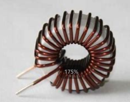
SubscriberPlease help me, now I want to simulate the magnetic ring as shown in the Fig.1 under the transient field, I have a problem on the excitation coil, I don't know how to set the excitation surface. (The number of turns of the excitation coil of the magnetic ring is 200)。
Figure1. Physical picture of magnetic ring
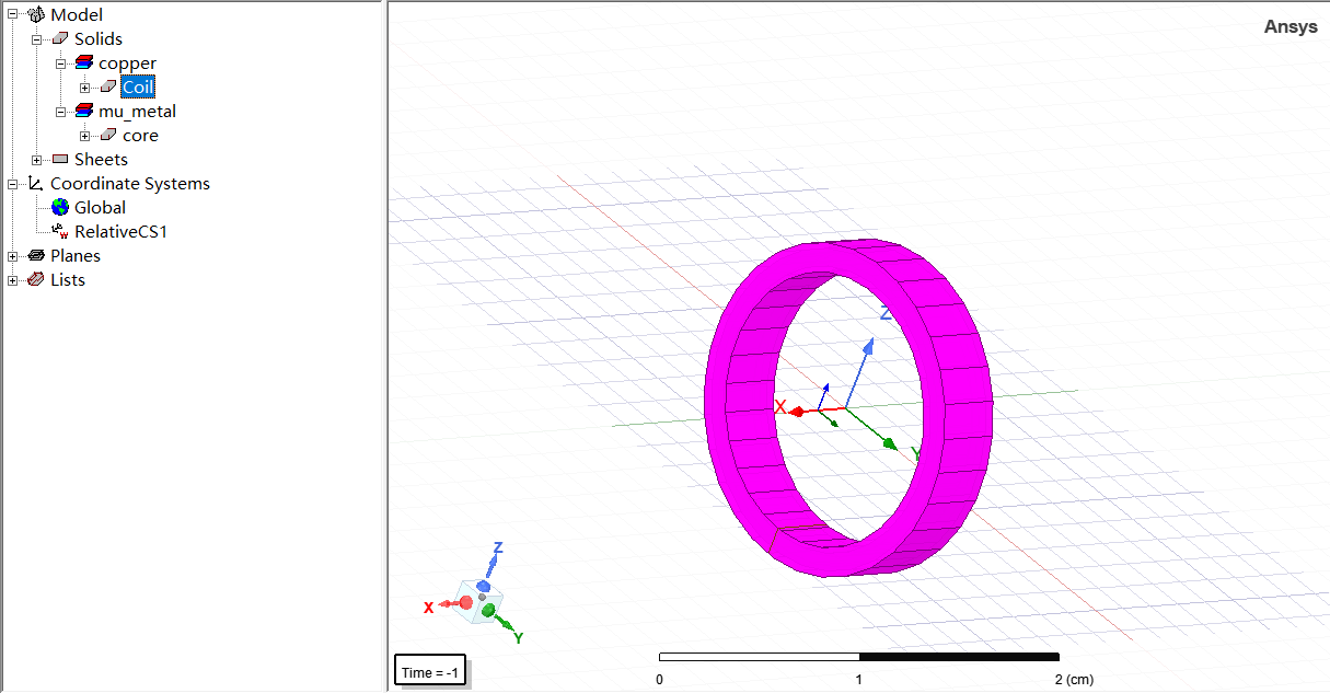
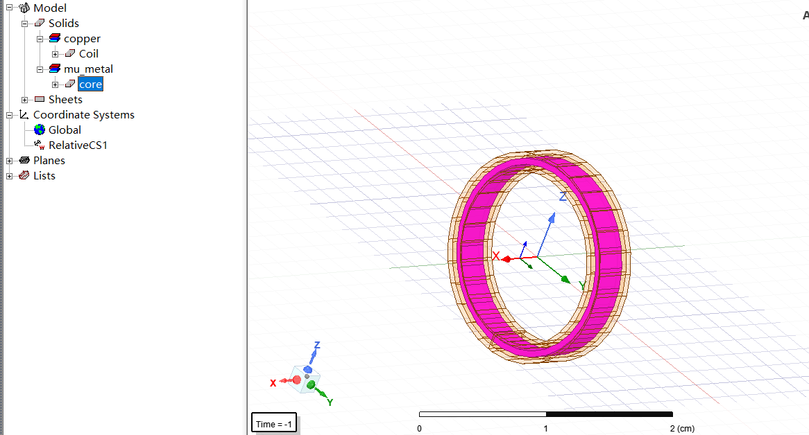
Now I have established the corresponding model in Maxwell. The orange area is the 200-turn excitation coil, and the gray area is the magnetic core (they correspond to Fig.2 and Fig.3).
Figure2. Excitation coil model
Figure3. Core model
Next, please instruct me, how should I set the excitation surface to ensure the correctness of the excitation coil? Am I setting the excitation plane correctly in Fig.4 ? >~<
Figure4. Excitation surface setting
-
May 24, 2023 at 1:36 pm
NKC
Forum ModeratorHi Liu ShuJun,
You need to section the coil in the YZ plane, not the XZ plane.
Regards,
Navya
-
May 24, 2023 at 1:53 pm
-
-
May 24, 2023 at 1:59 pm
NKC
Forum ModeratorYes,
Always section perpendicular to the current direction in the coil.
-
November 23, 2023 at 6:13 am
zcs19991114
SubscriberHello ,did you solve the problem? I have the same problem. I bulit the same core and coil,and I set the excitation surface in the YZ plane . Finally, i got a error "Process '3dtds' terminated abnormally. It may have run out of memory or could have been killed by the user",but I have the enougth ram ,it is 64GB
-
-
November 22, 2023 at 3:24 am
zcs19991114
SubscriberHello ,did you solve the problem? I have the same problem. I bulit the same core and coil,and I set the excitation surface in the YZ plane . Finally, i got a error "Process '3dtds' terminated abnormally. It may have run out of memory or could have been killed by the user",but I have the enougth ram ,it is 64GB.
-
- The topic ‘How to set the excitation surface of excitation coil in magnetic ring?’ is closed to new replies.


-
4678
-
1565
-
1386
-
1242
-
1021

© 2025 Copyright ANSYS, Inc. All rights reserved.


