-
-
May 23, 2023 at 11:50 pm
wancheng gao
SubscriberHi there,
I am using ANSYS 2022 R1, and I am not quite familiar with the APDL commands, So I want to ask for help whether i can define ANISO material for a bunch of parts in workbench using APDL command like below.
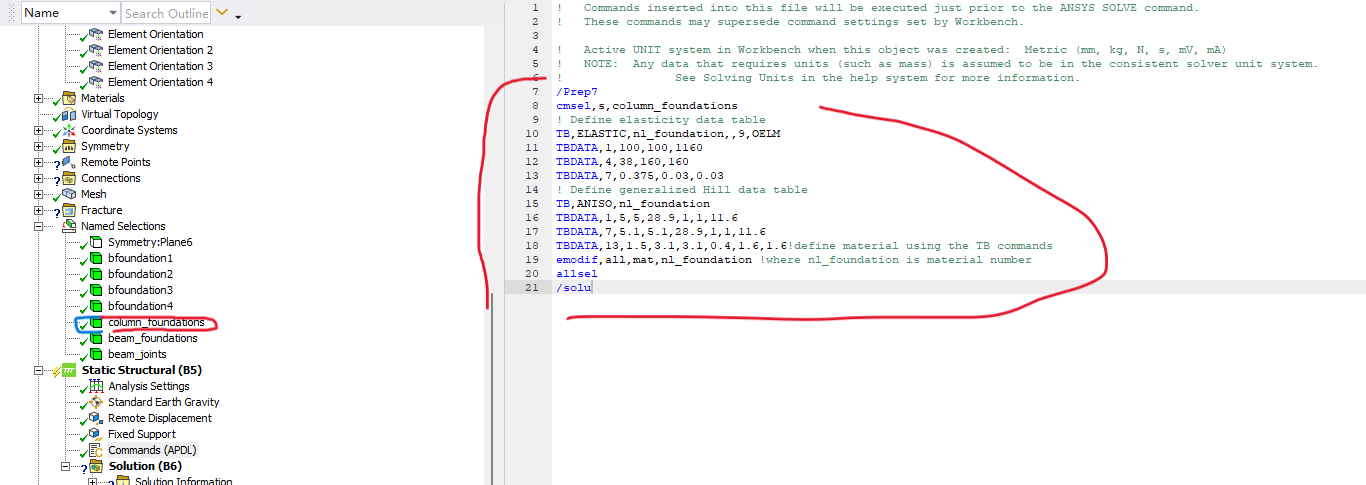
Step1, I created a named selection (which is called "column_foundations") for all parts needed to be assigned this ANISO material property;
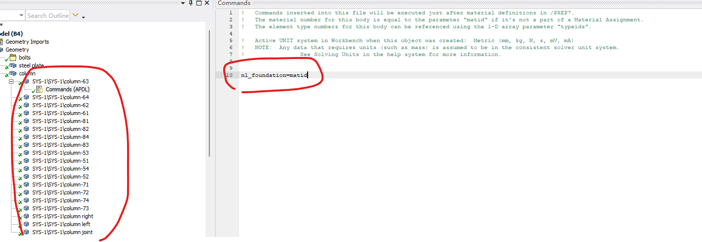
Step2, I inserted a command snippet under the first body and gave the matid a specific name "nl_foundation" (as shown in Fig.1).
Step3, I inserted another command under Static structural as below, to define all elements in the named selection (column_foundation) as the "nl-foundation" ANISO material;

Can anyone let me know whether the steps are correct? Any explanations are greatly appreciated.
Eason
-
May 24, 2023 at 12:18 pm
Chandra Sekaran
Ansys EmployeeThis looks correct!
-
May 24, 2023 at 6:14 pm
wancheng gao
SubscriberHello Chandra, thank you for your confirmation! May I follow to ask one more question?
Since it is ANISO material, so I created an local coordinate system to define the x y & z material principle axes. In the end I want to extract the stresses in the local x, y and z elemental directions. However with the force increasing the whole body would rotate but the local coordinate system which defined the x, y &z axes, seemed not to rotate with the body.
Would the elements defined in this way have their elemental coordinate system to rotate with the body? I read some posts on elemental orientation that may work and I am wondering whether you could give me some guidance on it. Your help is greatly appreciated!
Eason
-
-
May 24, 2023 at 7:46 pm
mjmiddle
Ansys EmployeeIf you turn on large deflection in the analysis settings, the element coordinate systems rotate with the rigid-motion deformation portion of the elements (probably just the average of the node movements when measured as rotations from the element centroid). The nodal coordinate systems will not rotate. If you insert a “Coordinate Systems > Elemental Triads” result, you can confirm:
-
May 24, 2023 at 8:37 pm
wancheng gao
SubscriberHello MJ, appreciate your reply!
My model is gonna take a long time to run so I just wanna confirm a little bit.
Yes the large deflection is on for my model.
As I mentioned in the post, an ANISO material is created. But not all the bodies are oriented the same way. How can I define each of them properly? What I have done is followed here, plz help me to check if it makes sense.
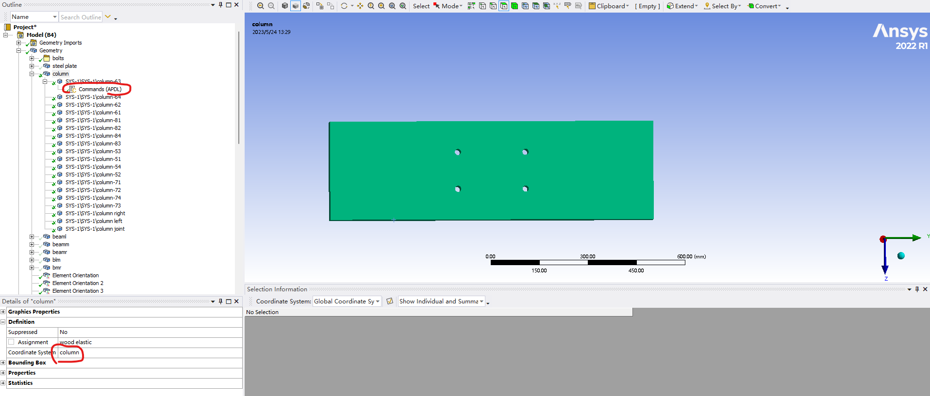
Since the ANISO material property is input using APDL command snippet. But I did not include any coordinate system in the command snippet. Should I define the coordinate for the body in the "Details of ** section"? If so, do I still need to use element orientation to this body to gurantee the elements have their local coordinate system rotate with the whole structure?
Thank you so much and expecting your professional advice!
Eason
-
-
May 24, 2023 at 9:32 pm
mjmiddle
Ansys EmployeeYou should be able to answer these questions yourself, by making a simple block model, with large deflection, and plot the element triads. Set a different coordinate system on the body. Set loads to deform the body a visually detectable amount.
-
May 24, 2023 at 9:43 pm
mjmiddle
Ansys EmployeeSince you are using workbench Mechanical, and your APDL snippet does not redefine the element coordinate systems, then you are accepting them exactly as Mechanical always sets it up.
Solid bodies will have element CS oriented by global CS by default. Reduced geometry (shells and beams) must enforce certain geometrical directions (shells have Z normal. Beams have X along length). Setting a different coordinate system than global CS on the body in the Details will set the element CS on all elements in the entire body to the directions of the selected CS. You typically only need to use an "Element Orientation" when you want a changing orientation across the body: a curvy shell body where Z must be shell-normal, but you want to change X,Y directions. An "Element Orientation" may also be necessary to reorient mesh based input from "External Model" system, where synthesized geometry is read-only. Element deformations during analysis rotate with the elements in large defetcion analysis regardess of CS assigned or "Element orientation" used.
-
May 24, 2023 at 10:31 pm
wancheng gao
SubscriberHello MJ, that is awesome that your reply confirms what I have set up is correct except that the element orientation part is unnecessary!
One more question, if I want to obtain the three stresses components in elemental CS, I have to switch to "Solution coordinate system", am I right?
Thank you!!!
-
-
May 24, 2023 at 10:59 pm
mjmiddle
Ansys EmployeeThat is correct. Set that in the result object.
-
May 25, 2023 at 4:59 pm
wancheng gao
SubscriberGreatly appreciate your time on answering my questions!!!
-
June 2, 2023 at 2:05 pm
wancheng gao
SubscriberHi mj,
A new question comes up. There are 12 load steps. Should I set up the "step selection mode" of the APDL command snippet to "all" ? Or just to "First" would be enough. I tried to set it to "All" and tried to analyze the model, but the analysis was terminated at the commencement of the 2nd load step.
Could you tell me how to use APDL command to define the ANISO material for all 12 load steps?
Thank you!
-
-
June 2, 2023 at 11:55 pm
mjmiddle
Ansys EmployeeYou only need to do the material commands for the first step. They will not change for the other steps. That usage is for changing loads and support, possinble contact. While you could change material properties in later load steps, I think that is unusual. Maybe for a fluid experiencing phase change.
-
June 4, 2023 at 3:13 am
wancheng gao
SubscriberThank you Mj, that helps me out!
-
-
- The topic ‘Inserting a command in WB to define nonlinear orthotropic material’ is closed to new replies.


-
4618
-
1530
-
1386
-
1209
-
1021

© 2025 Copyright ANSYS, Inc. All rights reserved.


