Ansys Learning Forum › Forums › Discuss Simulation › General Mechanical › How should 1-D FEA analysis be evaluated? › Reply To: How should 1-D FEA analysis be evaluated?
Hello KulTigin,
Beam models are the highest level of abstraction and have the most simplifying assumptions. For example, the uniform cross-section cannot change due to deformation. Shell models are a middle level of abstraction and have fewer simplifying assumptions but have limitations, such as they are only appropriate for thin-walled structures. Solid models have the lowest level of abstraction and the fewest simplifying assumptions and limitations. Each type of model is useful for different purposes. For example a beam model may be easier to parameterize for design optimization than the shell or solid model.
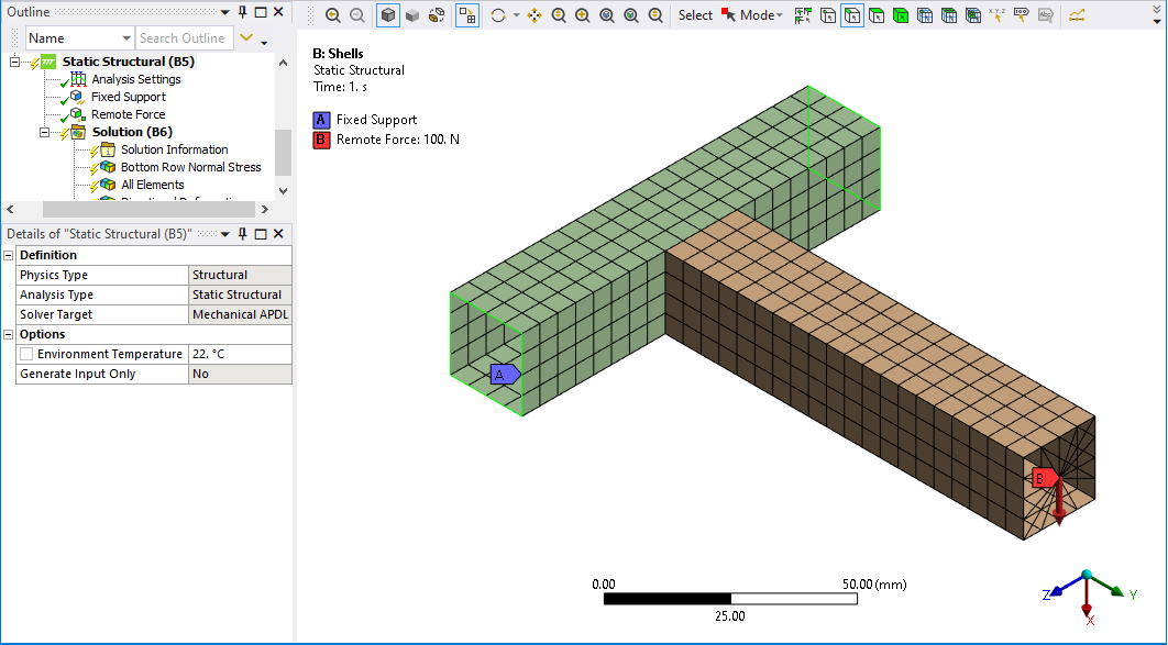
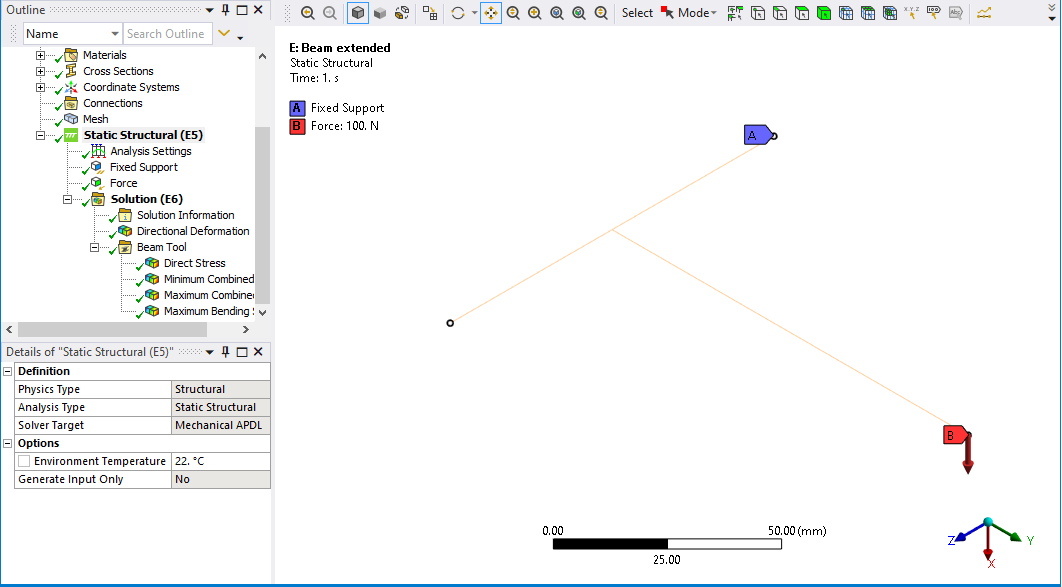
Your geometry has one beam connecting at a right angle to the center of another beam in what is called a Tee-intersection. In your beam model, the vertical beam was extended to reach down to the neutral axis of the horizontal beam. In the shell model, the vertical beam ends on the top of the horizontal beam. I made a similar Tee-intersection model and meshed it with shells and beams to illustrate my results.
The beam model is most honestly represented as a stick model.
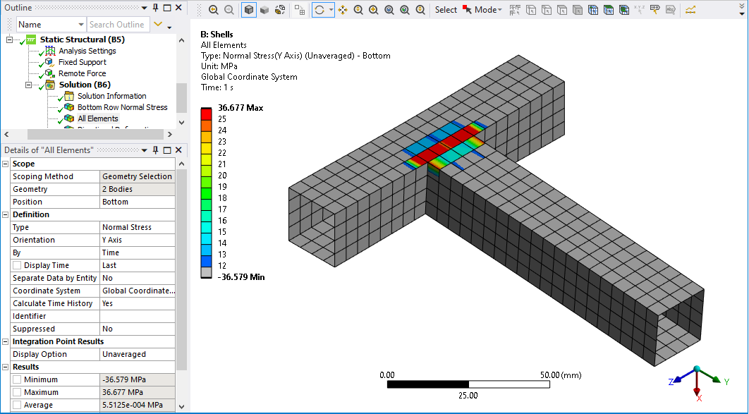
When comparing stress results you must compare similar stress quantities. The Beam Bending Stress is along the length of the beam at the extreme fiber. That direction of stress is the Normal Stress in the Y direction in my shell model.
The shell element Normal Stress in the Y direction for my model is shown below. Notice that the highest stress in the shell model is in the row of elements in the left tube, while the right tube has lower values of stress. The beam model can’t grab elements on the side of the left tube like it can in the shell model because the tube has been idealized to a beam element, so the highest stress in the shell model is not relevant to compare with the beam model.
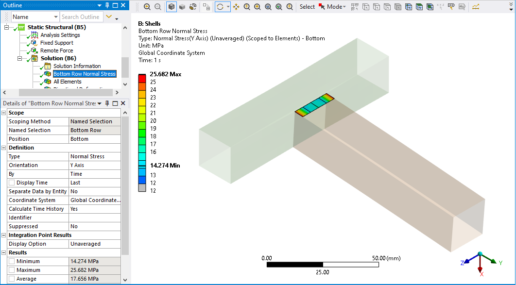
Look at the stress in just the 4 elements at the bottom of the right beam.
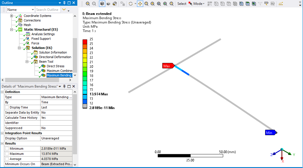
In the shell model, the minimum stress value of these four elements is 14.3 MPa and the average is 17.6 MPa. The beam model stress results below show the maximum value is 14.0 MPa which is at the center of the left tube, but the shell model doesn’t connect there, it connects at the surface of the tube. The beam element at a similar location to the shell model has a stress between 12 and 13 MPa. Note also that the beam element has a single stress value over the cross-section, while the shell model shows variation from the edges of the section to the center of the section, which the beam model can’t do.
I hope this helps to explain that the difference between the stress of the beam and shell models is in the range of 20%, not 100%, and that because of the different assumptions and modeling idealizations, you should not expect to get the same results from a shell and a beam model for this geometry.
Regards,
Peter
