-
-
December 8, 2017 at 5:24 pm
José Mantovani
Subscriber
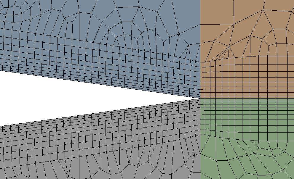
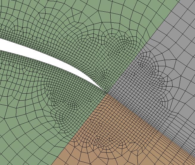
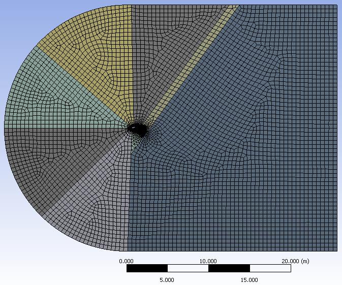
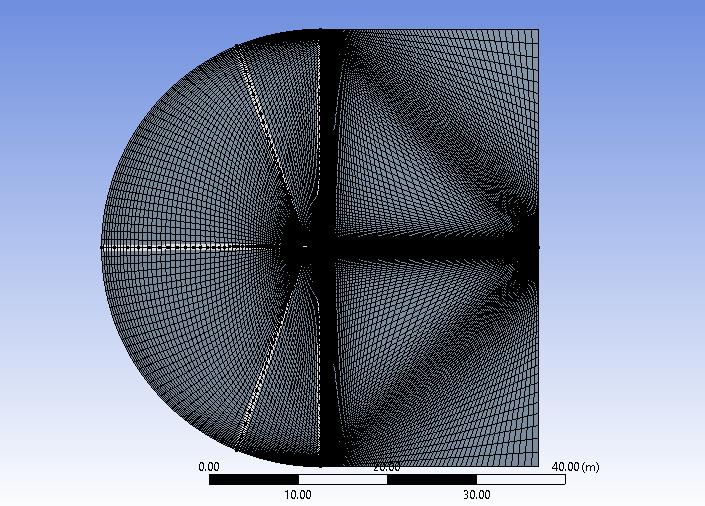
Gentlemen, I am trying to converge the value of the numerical result of the lift coefficient for the experimental result of the airfoil S1223. I've tried it in several ways and am getting values between Cl = 0.95 and Cl = 0.98, but the experimental value is Cl = 2.23. This for conditions of approximately Re = 380000 and an angle of attack alpha= 10 degrees. In my opinion the problem is the mesh, particularly at the trailing edge of the airfoil ... How can I improve the mesh in this region? I think that if a simulation was done in the edX course for a validation case of the NACA0012 airfoil with a relatively simple mesh and cells similar, we can see in below image, in the trailing edge region, I can also obtain a numerical result close to the result experimental, performing knit procedure in the same way ...
ÂOr does anyone know what can be done so that the value approaches the experimental value?
 ÂGentlemans, thanks for help and attention!
-
December 8, 2017 at 9:15 pm
-
December 9, 2017 at 2:31 am
-
December 9, 2017 at 2:34 pm
José Mantovani
SubscriberThank's so much Peter! Very nice!!!
-
December 14, 2017 at 2:53 pm
peteroznewman
SubscriberMantovani,
I read Vishal's answer to your other question, and watched the video he recommended and learned how to calculate the first element thickness using a Y+ calculator. For your Reynolds number and the air properties in Fluent, I got a first layer thickness of 5.6e-2 mm. The video also used 60 layers of inflation. You should update your mesh to these values.
Regards,
Peter
-
December 14, 2017 at 3:01 pm
José Mantovani
SubscriberBut Peter, I need update my mesh ou the mesh you sent me by email?Â
-
December 14, 2017 at 3:26 pm
peteroznewman
SubscriberYes, I just watched that video this morning, didn't you watch it last week?
-
December 14, 2017 at 5:35 pm
José Mantovani
SubscriberI had seen yes, even tried to apply my meshes, the values that I obtained in this calculator of Y +. I run the simulations here and the value was close to the experimental one, it's acceptable, I'll change it and see it gets even closer. Many thanks for the help Peter! Really, thank you so hiper very much! Come here to Brazil for we drink some beer! hahahahaha
Hugs.
-
December 14, 2017 at 7:51 pm
peteroznewman
SubscriberI have been fighting with inflation and gave up. I am now doing face meshing with biased edge sizing. I have the first layer thickness < 0.05 mm.
I have a nice "inflation" layer manually created after slicing the geometry.
I extended the domain to the size recommended in the video.
I'll send you this file.
Cheers,
Peter
-
October 5, 2018 at 7:11 pm
sai193272
SubscriberDear Peter,
Thanks so much for the advice to partition the domain. I am working currently on a 2D airfoil and have been trying to implement what you did on the S1223 in order to fix the skewness at the trailing edge. However, after splitting the domain (using split face) in design modeller and applying inflation to the airfoil and the new intersections, the mesh fails. If possible, can you detail your procedure slightly more?
Thanks very much in advance!
Sergio
-
October 5, 2018 at 7:57 pm
José Mantovani
SubscriberHello dear sai.
I exactely tested this approach to make a mesh to S1223, whats is sligthy different compared with NACA0012, because the S1223 is a no symmetrical airfoil.Â
At link below, have a way to how make a mesh to a not symmetric airfoil, in the case Clark-Y, but you can use this approach to do a similar mesh for S1223 airfoi. This PDF is a document of CFD Class of Iowa University.Â
http://user.engineering.uiowa.edu/~me_160/CFD%20Labs/Lab2/Intermediate%20Lab%202%20Manual.pdf
I hope helped you. Good weekend.
Mantovani.Â
-
October 8, 2018 at 12:20 pm
sai193272
SubscriberHey,
Thanks very much!
I tried implementing it but I get this weird mesh where the element size becomes larger initially (which it should) but then becomes smaller again towards the inlet. I made sure to assign the same number of divisions along the edges and used the same biases on parallel edges.
as a result, elements become skewed rather than being rectangular as in the example.
Do you know what the issue could be?
Thanks again in advance, much appreciated!
-
October 8, 2018 at 12:28 pm
sai193272
SubscriberIt seems my settings are being overridden somehow, changing bias for example has no effect at all
-
October 8, 2018 at 12:58 pm
José Mantovani
SubscriberThis is due to the proportion of Edge Sizing. It seeks to correlate a ratio with the size of the domain. Try replicating exactly like the link I submitted. Use even the same domain size and replicate size limitations. See what happens.
I do not think I have the file with the mesh here, I'll take a look. Try to do this and share here if you have succeeded, if not, I search my files and show you.
Mantovani.Â
-
October 8, 2018 at 1:17 pm
sai193272
SubscriberIs there a way to increase the domain size and maintain the same ratio as in the Iowa example? The airfoil used in the example has a cord of roughly 0.300m. The one I am trying to analyse is about 8 times as large.
-
October 8, 2018 at 1:50 pm
José Mantovani
SubscriberSo, use this to create your domain. Where is one in the Iowa example, in your will be eight. Ok?Â
In aerodynamic analysis is usually use the chord length around 1 meter. You can also change the chord length of your aerodynamic profile S1223. Â
-
October 8, 2018 at 1:56 pm
sai193272
SubscriberThat doesn't work unfortunatley.. The result looks similar to the picture above (with a finer mesh).
Is there perhaps a way to prevent the program from automatically seeking to relate the domain size to edge size?
Thanks for your response!
-
October 8, 2018 at 2:06 pm
José Mantovani
SubscriberYou are having these errors because you are putting different values for number of divisions. Ensure that the values of the region behind the airfoil, the square region of the domain are with similar values for vertical edges with vertical edges and horizontal with horizontal edges. The vertical edges must have the same dimensions as the edges that are directly attached to the C part of the domain. If you have a domain with a height of 50 m and you define division numbers to 47 you will surely get this error. Look for exact values, or in relation to your domain.
For example, if you have a domain of a rectangular channel of 5mx10m and use division numbers of 7x14 you will have a mesh similar to yours.
-
October 8, 2018 at 3:32 pm
sai193272
SubscriberRight. I took that into account bu the problem remains.
If you don't mind, can you have a quick look over my mesh file? Maybe there is something obvious that I am missing.
-
October 8, 2018 at 4:25 pm
José Mantovani
SubscriberI will try to make a mesh over S1223 geometry here, because I lost the files of this simulation. So on I share here.Â
-
October 8, 2018 at 4:56 pm
sai193272
SubscriberThanks, that would be amazing!
-
January 18, 2019 at 11:37 am
Vinod Kumar
SubscriberHello Peterozenewman, Can you please tell me about this "Â slice the surface at the trailing edge". I am facing the same problem high skewness near sharp edges/trailing edge.Â
-
January 25, 2020 at 1:49 pm
mjameel
SubscriberHello Peter, can you share with me the Video? I am also dealing with an airfoil with an extended span (thickness). I tried all the necessary methods in the Fluent meshing but am still having a problem with limitation of inflation in relation to Multizone method and face meshing method.Â
-
January 25, 2020 at 2:52 pm
-
March 11, 2020 at 2:13 am
AravindReddy
SubscriberHello peteroznewman ,
Â
i have a similar problem but my airfoil is inside the 3D domainÂ
could you please look into this postÂ
-
April 1, 2020 at 7:50 am
singh33
SubscriberHi mjameel,
I was reading one of your discussions on Extended Flow I am doing the same on the flow over the circular body making that C-grid Mesh only, I want your guidance for the generation of the periodic boundary in the spanwise direction i.e. Z-direction in ICEM CFD. That discussion is closed by Mr. rwoolhou so I asked the help from you here I hope you do not mind.
Â
Thanks and Regards
-
- The topic ‘Converge the numerical result’ is closed to new replies.
- CONVERTING STL FILE IN TO SOLID
- The meshing algorithm cannot find matching topology
- How do I fix this irregular face meshing problem?
- [ANSYS Meshing] how to activate curvature for a sizing in a script?
- ICEM O grid mesh for sloped pipe
- How to create a mapped mesh in a chain link model with stud.
- what is the best way to apply shear stress to a shell 181 element?
- Meshing Help – I keep getting errors. How would you tackle this geometry?
- Solutions for “A software execution error occurred inside the mesher.” in 2D
-
2432
-
930
-
599
-
591
-
569
© 2025 Copyright ANSYS, Inc. All rights reserved.