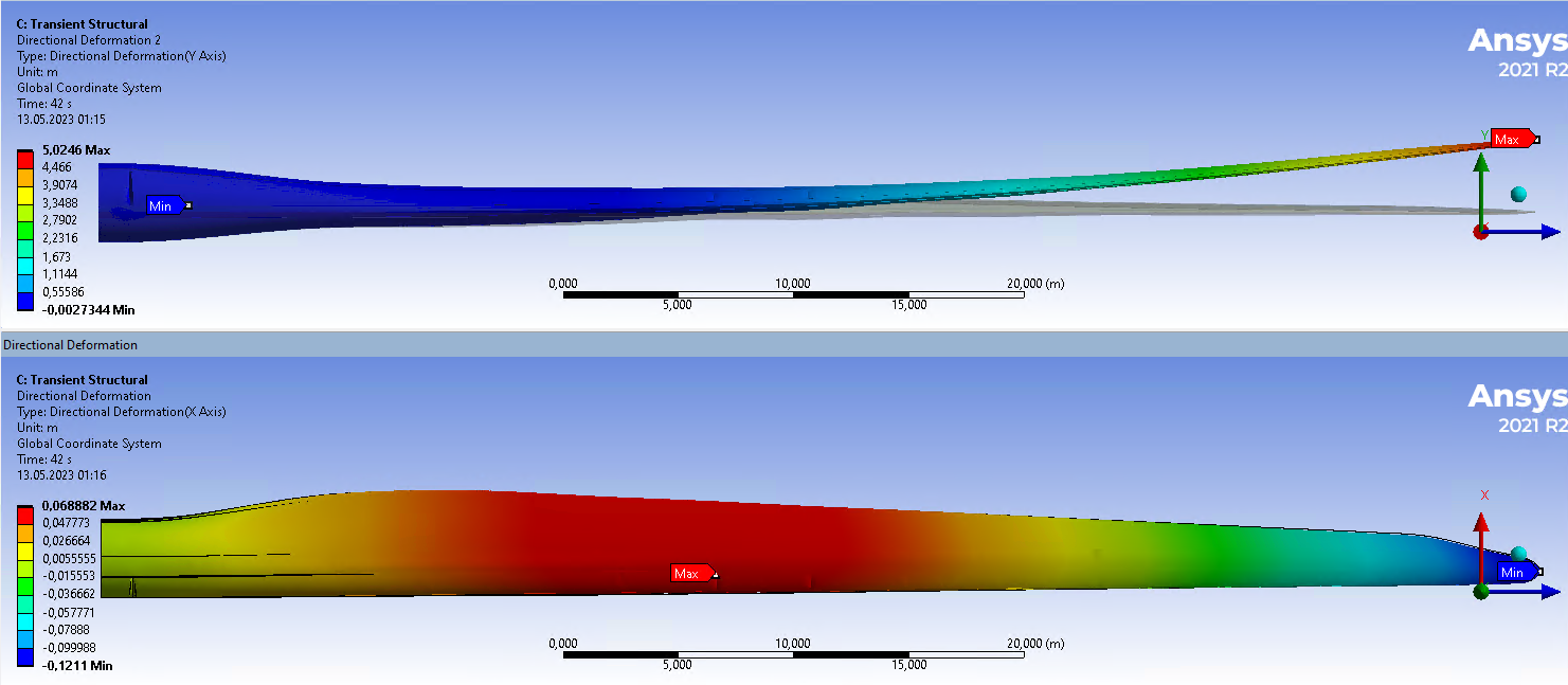
The X directional deformation of the root is 0, the tip is X = -0.121 m while the center is X = +0.0688 m. You ask why the minimum is not at the root, but the root doesn't move while the tip moves in the -X direction relative to the root and the middle moves in the +X direction relative to the root.
If you sum the pressure over the profile at every 1 m long station along the wing span and decompose the sums into Fx and Fy, you will see how the forces cause deformation in the X and Y directions. The forces interact with the bending stiffness in each direction and result in the deformation shown in the plot. Does that make sense now?
The Y directional deformation of the root is 0 and the tip is Y = 5.02 m.