-
-
November 1, 2017 at 6:22 pm
MaxKL
SubscriberHello,
As part of a Student Research Project at my University, I am to model a pointbased facade panels. My Problem now is that no matter how deep I choose my embedment depth of the pins in the attachment shell, the tension around the pins (in a radius of 6cm -10cm) exceeds almost 2 to 3 times the expected value. I've already tried in the Problem area to perform a mesh refinement to 3mm, or round off the Pins. Everything without success. Now my question to you. Does anyone have any ideas or suggestions for me ?
The Maximum stress can/could be 20-22 MPa. Also i want to know if I can transform my Modell into a 2D-Plate with 3D-Pins. Like this
My problem here is that I get a Pivot-Error at the resault. I think its a problem in the contact section, because i cant see any contact Areas if i do 2D-plate and 3-Pins. I'm working t´with the DM. Information about my Project: 1.3mx1.3mx0.03m (plate) Insertion depth of the connecting means: between 0 and 3cm The facing shell (plate) is made of UHPC and is loaded with a Surface load of 0.08MPa (value determined in the laboratory) The pins (made of fiberglass-reinforced plastic) have a Diameter of 12mm and the distance between attachment shell (plate) and tray is 200mm


Best regards
Max
-
November 1, 2017 at 6:23 pm
MaxKL
SubscriberBy the way i dont think ist a singularity.
-
November 1, 2017 at 10:11 pm
peteroznewman
SubscriberHi Max, this looks like an interesting project.
I recommend using symmetry to reduce the size of the model to 1/4 of the whole. The symmetry boundary conditions will also help to support the model.
I looked at this webpage to learn about point-supported facades. Their panels are glass with holes where metal pins with shoulders and fasteners clamp the glass to the pins.
How do your glass-filled plastic pins contact the UHPC panel (shell)?
You say you embed the pins in the panel . Do you mean there is a blind hole in the panel where the pin is inserted?
You say the pin is 12 mm in diameter. What is the diameter of the hole in the panel ?
Are the pins bonded to the panel with an adhesive?
The answers to those questions will decide if you can model the panel using 3D shell elements meshing a sheet body, or if you have to use 3D solid elements meshing a solid body. If the pins go into a blind hole, then you must use solids.
Do the glass-filled plastic pins also go in holes in the support block?
What is the diameter of the holes in the support block?
What is the support block material?
Best regards,
Peter
-
November 2, 2017 at 1:01 pm
MaxKL
SubscriberHi Peter,
thank you for your quick Response. Maybe I can use the symmetry for the first part of my project but later i want do do a Parameter study with size of every pin and their angle to the plate. So in my opinion i cant use it.
For the Connection with the UHPC Panel and the Support block:
When we are concreting the UHPC Panel(Shell) the glass-filled plastic pins are already fixed in the the shuttering. After the concrete has dried the plate is rotated 180° and the other side got fixed in the Support block shuttering. Then we are concreting it with a c50/60. So for the bond between the pins and the Panel/Support block is just the bonding of the concrete and no adhesive.
So i have to use Shell Elements ? If yes how can i do this ?
I hope i have answered all your questions.
Best regards,
Max
-
November 2, 2017 at 2:49 pm
peteroznewman
SubscriberHi Max,
Let me check my understanding.
- You have 12 mm diameter glass-filled plastic pins that will have concrete molded around them.
- The concrete panel is 3 cm thick and the pins can be embedded to some depth where the concrete will bond to them.
- The depth of the pins can be between 0 and 3 cm into the concrete.
- There will be a pressure load on the face of the panel and you are interested in the stress in the concrete.
Given that, I expect the peak compressive stress to be where the pin and concrete meet on the back of the panel, but the peak tensile stress may be on the front face of the panel. Therefore, you must build a 3D solid of the panel, with blind holes with a 12 mm diameter where the pins exist, and pins that fill those holes. The easy way to make the holes is to use the pins in a Boolean subtract. For a first model, you can put the all parts (9 pins and panel) into a single part in DesignModeler (Form New Part). That way, the mesher will create shared nodes at the coincident faces and that will "bond" the pins to the concrete without using contact in Mechanical. I would cut off the pins at the plane where they emerge from the support block and hold those faces fixed. Don't even model the support block. Add pressure load on the front of the panel.
You must ensure that there are at least two layers of solid elements in the thickness of concrete that matches the depth of the holes, and two layers of elements in the pin that is in the hole. These conditions will avoid "pivot" errors from the solver. An easy way to ensure the two layer minimum is to create a plane at the bottom of the hole and slice the concrete at that plane. You can then sweep that body in meshing and specify the number of elements. You might want an lot more than two elements to resolve the peak stress. Do the same with the pin by creating a plane on the back face of the panel, and use that to slice all the pins.
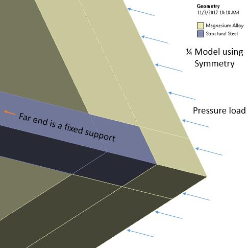
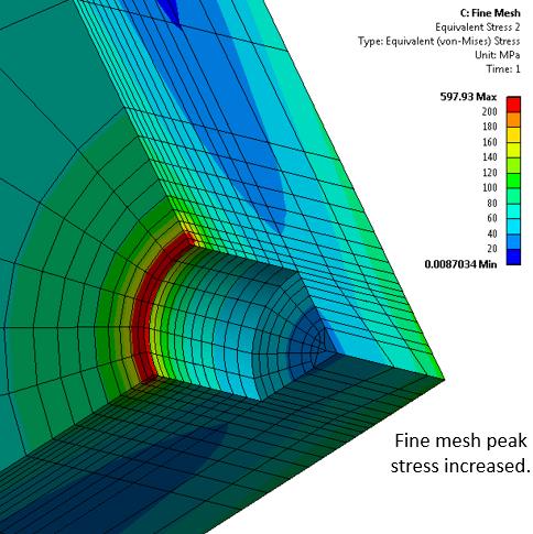
Since it is concrete, I expect the compressive strength is much higher than the tensile strength. You might consider how you will calculate a failure metric that accounts for this difference in strength. Also, what about gravity? Doesn't the weight of the panel deform the pins in a vertical orientation of a panel? Finally, I do think there is a singularity in the model I described, since there is a sharp interior corner at a point of high stress.
Best regards,
Peter
-
November 5, 2017 at 1:57 pm
-
December 26, 2018 at 2:34 pm
naveen28
SubscriberHi Peter,
I too encountered the singular stress few times. In this case, what will be your suggestion to avoid this singular stress?
And what changes we can make to get the actual stress values?
Thanks,
Naveen
-
December 26, 2018 at 3:40 pm
peteroznewman
SubscriberHi Naveen,
In this case, I would add plasticity to the Magnesium material and it would yield at the high stress areas and that would resolve the singularity.
If you want to ask about one of your cases, please start a New Discussion. When you do that, you will "own" the discussion and receive email updates (if you want) that a new post was made on your discussion.
Regards,
Peter
-
- The topic ‘Too high stress in a plate’ is closed to new replies.


-
4969
-
1645
-
1386
-
1242
-
1021

© 2026 Copyright ANSYS, Inc. All rights reserved.


