-
-
October 29, 2017 at 9:06 pm
peteroznewman
Subscriber
If your model includes a threaded fastener, the simplest model is to use bonded contact to bond a smooth rod that represents a threaded fastener to a smooth hole that might represent a tapped hole or a threaded nut.
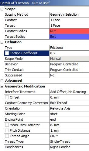
A more sophisticated treatment is where the smooth rod and hole have a thread geometry treatment applied in the frictional contact definition. This is more realistic than bonded contact for deformations on the surrounding parts since the stress builds up in the first few threads in a more representative way than the bonded contact which is less realistic. The smooth cylindrical hole had the contact geometry correction of Bolt Thread applied in the contact definition.
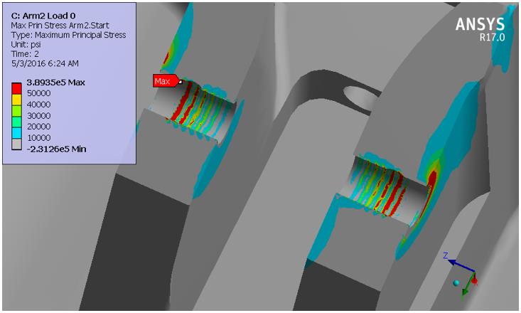
The image below shows two holes with a shoulder screw (hidden) tightened down on the outside face. This model is not intended to be a very accurate calculation of the stress in the treads. That is what a detailed model using actual thread geometry is for. This model distributes the force through the parts in a more realistic way than simple bonded contact.
It is recommended to have a mesh density of at least four elements per thread pitch.
Another post has an example of how to evaluate failure in the threads themselves.
-
July 16, 2019 at 12:47 am
DerRepeater1
SubscriberHi Peter,
I'm doing a same simulation using bolt threaded option of ansys, and the stress result is greater than the ultimate stress of the bolt's material.
Is the diameter of the cylindrical surface represents the thread of the bolt? When I set this option, is the thread actually will have a larger radius than the current face that leads to high penetration problem? The contact status is "closed" as I've checked it via contact tool.
-
July 16, 2019 at 1:17 am
peteroznewman
SubscriberHi,
Make the diameter of the hole and the diameter of the fastener equal.
You must have a mesh density of at least four elements per thread pitch. It doesn't look like you have done that. If the thread pitch is 1 mm, then you must have a minimum of 4 elements per mm along the length of the fastener and the hole.
-
July 16, 2019 at 1:01 pm
DerRepeater1
SubscriberThanks Peter,
The mesh density requirement is a big problem, I plan to split the bolt into 2 bodies, the threaded body is meshed with required density, the other will contain coarse mesh, then I set "bonded" contact between 2 bodies. Do you have any experience with this solution?
-
July 16, 2019 at 2:59 pm
peteroznewman
SubscriberLook carefully at the original post and you will see that it is Frictional Contact, not Bonded Contact.
I know it seems weird to use frictional contact on a shaft and hole, it seems it would just slip out, but that is what the Contact Geometry Correcction = Bolt Thread does, it creates, under the hood, the pressure angle of the thread at the contact surfaces so that the two sides can push against each other when there is an axial load on the shaft.
-
- The topic ‘Simple method for simulating local deformation near fastener threads’ is closed to new replies.


-
4602
-
1510
-
1386
-
1209
-
1021

© 2025 Copyright ANSYS, Inc. All rights reserved.


