-
-
October 4, 2017 at 12:49 pm
omarjumaah
SubscriberHello all,
I need to draw equation driven curve in designmodeler, then optimize it. any hints are valuable to me. thank you in advance,
Omar
-
October 5, 2017 at 10:32 am
-
November 5, 2017 at 6:55 pm
omarjumaah
SubscriberThank you for replying. I appreciate your help.
-
November 5, 2017 at 8:42 pm
peteroznewman
SubscriberWhat is the equation and what parameters can be varied to optimize the curve?
What is the range that each parameter can take?
I use SIEMENS NX CAD system and can create parametric curves in that.
I can import that CAD file into DesignModeler and can include the parameters for a Design Optimization in ANSYS.
Do you have a CAD system or are you limited to working in DesignModeler?
-
November 7, 2017 at 10:54 am
cos2pi
SubscriberHi
I have the same problem, can you solve it by spaceclaim, or Solidworks.
I would prefer that it could be solved by design modeler, since i then avoid converting and importing issues with units and edges.
-
November 7, 2017 at 12:12 pm
Vishal Ganore
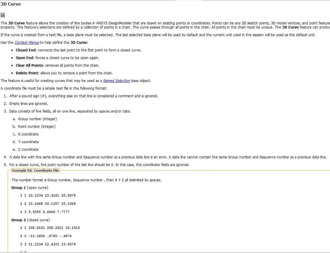
Ansys EmployeeIf you wish to use Design Modeler (DM) then please follow following steps:
1. Take your equation, convert it into coordinate points (x.y and z) governing that equation.
2. Write it into 3d curve usable format (see the snapshot that I uploaded before)
3. Create text file (sample: paste following into text file (.txt)
1 1 10.1234 15.4321 20.5678
1 2 15.2468 20.1357 25.1928
1 3 5.5555 6.6666 7.7777
4. Use 3d curve option from DM
5. Upload coordinate file
It will give you the line body for your future operations. All the best.
-
November 7, 2017 at 6:06 pm
cos2pi
SubscriberThank you for your reply,
Can i use the same method, if i want to create ít as a 2D sketch and then extrude?
The thing i wish to draw is a wavy channel coldplate. Where the wavy pattern is a sinusoidal function with variable amplitude and frequency.
So i need a thickness on the fin, and a height -
November 7, 2017 at 6:26 pm
Vishal Ganore
Ansys EmployeeYes, It is possible. Convert your curve into three points coordinate system (x,y,0). Z coordinate for all points will be zero.
-
July 16, 2018 at 10:24 am
Valeria
SubscriberI am importing a hyperbola from solidworks since I wasn't able to draw it in DesignModeler or SpaceClaim, but then in design optimization I cannot change one length of such curve as parameter because I think Ansys is not able to reconstruct the hyperbola.
Do you have any idea on how to design a hyperbola (from equation) in DesignModeler or Spaceclaim or how to make direct optimization tool modify the hyperbola without requiring user input ? (When it gives the error: user input required before it can be updated, I cannot modify anything in DesignModeler)
Does it work with txt file with points of the hyerbola?
Thank you,
Valeria
-
July 16, 2018 at 11:45 am
peteroznewman
SubscriberHello Valeria,
I suggest you construct a Conical surface and a Plane and use Slice to create the intersection curve, which is a hyperbola. Both the conic surface and plane may be parametrically controlled in DesignModeler or SpaceClaim from a Workbench optimization system.
Regards,
Peter
-
July 16, 2018 at 12:51 pm
Valeria
SubscriberThank you very much Peter, I didn't think about that. I tried to extrapolate the hyperbolic profile as a curve but didn't manage, any suggestions?
-
July 16, 2018 at 3:13 pm
peteroznewman
SubscriberHello Valeria,
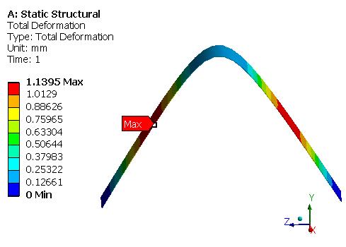
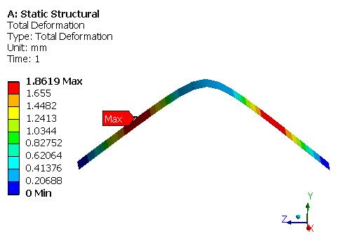
Attached is an ANSYS 18.2 archive that implements a cone sliced by a plane and the hyperbolic edge extruded as a thin arch. The cone angle is a parameter. Workbench can march through a Parametric Table of Design Points automatically.
Are you working on the free Student license which has no SOLIDWORKS bi-directional interface, or a Research license that includes the SOLIDWORKS bi-directional interface that allows SOLIDWORKS parameters to come into ANSYS?
-
July 16, 2018 at 7:53 pm
Valeria
SubscriberThank you very much Peter, I am experimenting now your suggestion. It's the one of University actually so I don't know, I think it's bidirectional as I have the Ansys add-in in solidworks and I'm able to import parameters frfom Soldiworks to WB.
-
July 17, 2018 at 1:09 am
peteroznewman
SubscriberYes, you have the SOLIDWORKS plug-in that allows bi-directional data exchange between Workbench and SW. That means you can do the parameterization in SW and drive that from Workbench.
-
July 18, 2018 at 8:42 am
Valeria
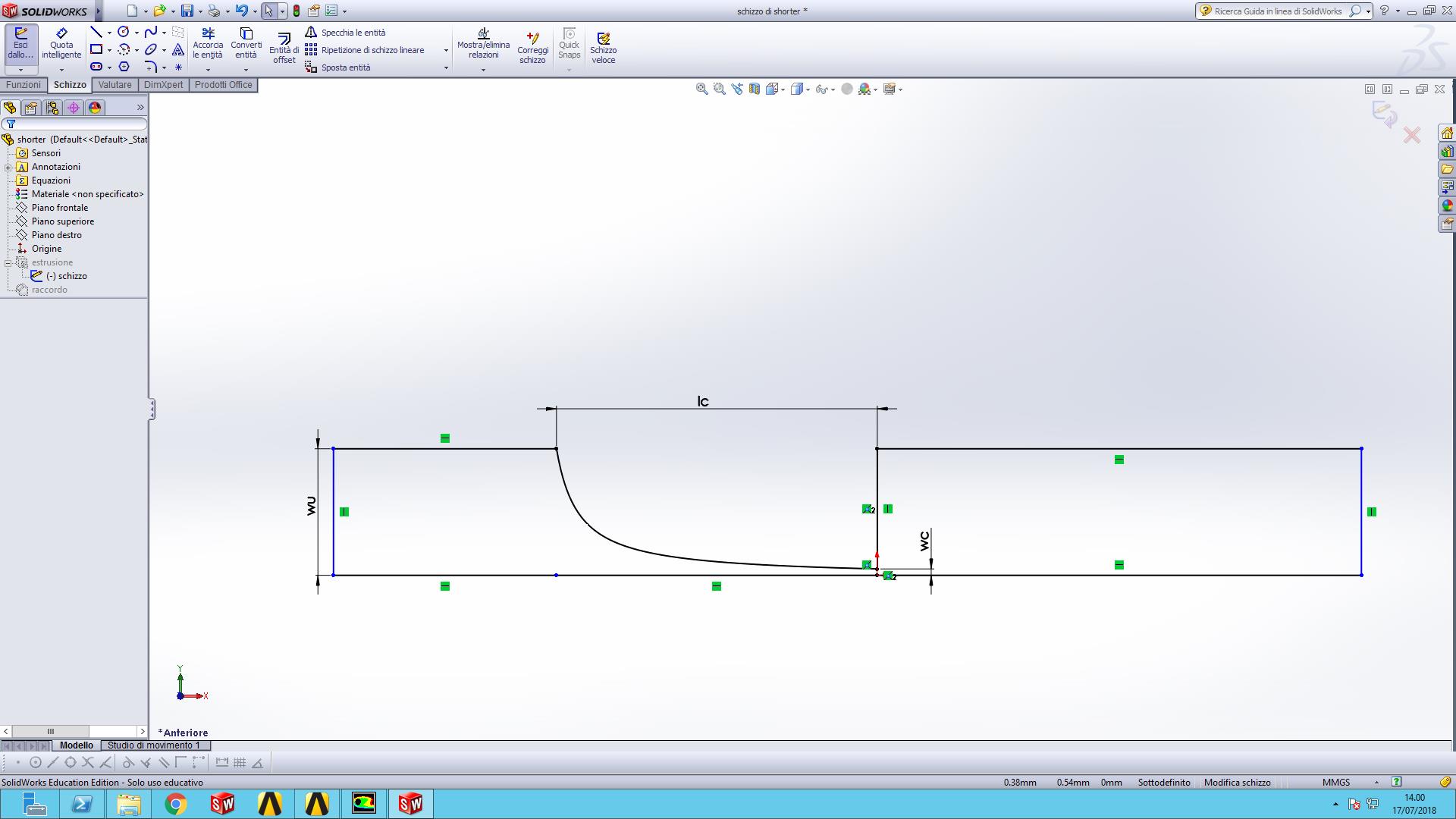
Subscriberyes I can but WB seems to be unable to update the parameters of the hyperbola probably because its equation is set in solidworks. This is a screen of what I'd like to draw inside design modeller, but I can't figure out how to set the cone angle and psition of the plane to intersect it in orded to obtain precisely the hyperbola of equation
y=0.2/(1+29.32(x+0.65))
-
July 18, 2018 at 10:32 am
peteroznewman
SubscriberHello Valeria,
I will dive deep into mapping an equation for a hyperbolic curve into a cone and plane.
I can show you how to have WB send SW parametric values to update the geometry, which is then sent back to WB. Please put the SW part (or parts and assembly if applicable) into a zip file and attach that after you post your reply and I will see if I can get that working. Also say what version of SW you are using, I have SW2017 installed.
Regards,
Peter
-
- The topic ‘parametric equation driven a curve’ is closed to new replies.


-
4818
-
1587
-
1386
-
1242
-
1021

© 2026 Copyright ANSYS, Inc. All rights reserved.


