Ansys Products

Ansys Products

Discuss installation & licensing of our Ansys Teaching and Research products.

Ansys AQWA-How to add fins for damping at our offshore marine structure?

    • pavlidisthrasuvoulos
      Subscriber

      Is it possible to add fins(or bilges) via inserting additional damping or nonlinear roll damping  for damping at Aqwa and if yes how exactly can it happen? or do we have to insert it through our drawing(i use spaceclaim) ?I want to add damping to my structure and i found it difficult ...Can anyone give me a tip or tutorial of how to do it?

      Thank you!

    • Mike Pettit
      Ansys Employee

      Hello Greg,

      You can use the Nonlinear Roll Damping definition to model roll damping due to bilge vortex shedding or the effect of bilge keels in a time domain Hydrodynamic Response analysis. This doesn't require you to change the geometry in SpaceClaim. Here's how:

      • add a Nonlinear Roll Damping object to your vessel: right on the vessel in the Outline tree, then Insert > Nonlinear Roll Damping
      • in the Details panel, change the 'Nonlinear Roll Damping' option from 'Use a Coefficient' to 'Define Bilge Parameters'
      • define each end of the central line of the vessel by manual definition, or by selecting vertices from the geometry
      • In the 'Bilge Roll Damping Details', you can set the bilge radius/depth/offset from the central line, and you can optionally define the bilge keel geometry if necessary.

      I hope this helps.

      Cheers, Mike

    • pavlidisthrasuvoulos
      Subscriber


      Thank you a lot!!! I tried yesterday and i couldnt do it.Why does it require bilge radius?I dont want circular element(rectangular only).Only dimensions(length,width and height) and thickness to have it along the low part of the structure.Not exactly at the keel.

      Thank you Mike!!


    • Mike Pettit
      Ansys Employee

      Hi Greg,

      The formulation used by Aqwa to estimate the nonlinear roll damping assumes that the vessel is 'ship-shaped' and symmetric, with a bilge radius and (optionally) symmetric bilge keels attached to the bilges at 45 degrees to the central line:

      If you only want bilge keel effects to be included in the nonlinear roll damping estimate, I would recommend that you:

      • set the 'Depth to Bilge' value to be very small (0.01x) compared to the 'Offset of Bilge from Central Line' value; this forces the bilge vortex roll damping coefficient to be very small, i.e. turns off the bilge vortex shedding component of the roll damping.
      • change the 'Advanced Bilge Keel Options' detail from 'Program Controlled' to 'Manual Definition', which allows you to position the bilge keels independently of the bilges.

      The graphical representation of the bilge keels in the Aqwa Workbench editor should hopefully give you an idea of when they are in the right place for your vessel.

      Cheers, Mike

    • pavlidisthrasuvoulos
      Subscriber


      I have the below project :

      Is it possible to insert 3 fins for roll-pitch damping above the heave disc?Does the above way help ?Or is only for ship shaped and symmetric vessels?I want the damping for a floating platform.

      Thank you again Mike!


    • Mike Pettit
      Ansys Employee

      Hi Greg,

      Sorry, this makes much more sense now. The Nonlinear Roll Damping definition is probably not much use here. To introduce nonlinear damping you should use additional Morison Disc elements, where each disc can be considered as a point Morison load on the structure. If you want to model damping along the length of each fin, you can use a row of discs.

      Cheers, Mike

    • pavlidisthrasuvoulos
      Subscriber


      Hello again Mike and thank you so for your time.Im sending an image of how i want the damping.Is it better to draw that at spaceclaim rather than trying to insert it here like i did with the heave discs or is there any way to insert those thin rectancular elements perpendicular to the spar(the black elements at the image below) in another way? Thank you again! 


    • Mike Pettit
      Ansys Employee

      Hi Greg,

      You can either model these fins using Morison Discs, as described above; or, you can create Line Bodies in SpaceClaim, assign them with rectangular cross-sections, and they will be modelled as Morison line elements in Aqwa. This will give you a more realistic appearance in the Aqwa Workbench window, though the actual results may be similar (depending on how you define the discs/line bodies).

      To create the line bodies in SpaceClaim:

      • start by sketching some lines either side of the spar, along the axis of each fin
      • in the Prepare tab, click Profiles, and from the New Profile Library select 'Rectangle' or 'Rectangular Tube'
      • in the Structure tree a Beam Profiles icon will appear. Expand this and right-click > Edit Beam Profile on the beam profile you just created
      • in the Groups panel, set the cross-section dimensions by clicking on Ruler Dimension for each dimension:

      • switch back to your platform geometry by clicking on the bottom tab in the graphical window
      • click to select the lines that you sketched previously
      • in the Prepare tab, click on 'Rectangle' (or 'Rectangular Tube' etc) to assign the current beam profile to the selected lines
      • in the same part of the Prepare tab, click the 'Display' dropdown menu and select 'Solid Beams' to show the beam profile on the model.

      Note that the Morison loads in Aqwa will only be calculated along the axis of each line body; you could create several adjacent line bodies on each side of the spar if you want to account for e.g. the variation in fluid velocity across the fin.

      Note also that the line bodies introduce their own mass to the model. If you do not want this, you can either:

      • set the beam cross-section to be thin in SpaceClaim, and/or
      • set the beam density to be small in Aqwa Workbench, by expanding Line Body Data in the Outline tree, selecting the appropriate beam section (e.g. 'Solid Rectangular 1'), and setting the Material Density value. You can also define the hydrodynamic properties (added mass/drag coefficients) here.

      I hope this helps!

      Mike

    • pavlidisthrasuvoulos
      Subscriber

      This really  helps!!.

      Thank you a lot Mike!

    • pavlidisthrasuvoulos
      Subscriber


      For making the line bodies NOT having mass ,you said that i have to set the beam cross section thin in spaceclaim.Is there any setting for that,or just to give thin dimensions u mean?Because i only saw thin shells choice from display(at prepare panel).There is no thin beam cross section choice.Is there any limit at the dimensions of the beam cross section to be considered thin or is there a setting for that?? eg I dont want to add more mass and to insert these elements like i do with the heave disks,so not to infuence the center of gravity and CoBuoancy with the addition of fins.I tried it…but the beam appears in the middle of the fin as  the below image shows:

      Is it a problem? And in the structure panel it shows(it doesnt appear the beams like line bodies):

      And as you said ,it adds mass….how can i have them(those fins) ,like the heave disks(without adding more mass)…???

      Thank you !!


    • Mike Pettit
      Ansys Employee

      Hello Greg,

      To answer your questions:

      • There is no way to create a line body with zero mass, but you can make the mass (and buoyancy) very small at least, by setting the rectangular cross-section dimension to be thin. I've tried with a thickness of 0.01 mm, and this works ok (though 0.001 mm does not! - SpaceClaim interprets this as zero). Combined with a small Material Density value in Aqwa Workbench (e.g. 0.1 kg/m^3), you should be able to make the fin very light. (If you really need to have exactly zero mass/buoyancy, you will have to use Morison disc elements instead.)
      • This is how beams always appear in SpaceClaim, so this is expected. When you import the geometry into Aqwa you should see the actual cross-section, with a black line drawn along the beam axis.
      • In the Structure panel in SpaceClaim, you need to arrange the beams so that they are nested under the main structure. Drag-and-drop each beam icon on to the main structure, so that the tree looks something like this:

      • You may also need to set the Share Topology option, so that the bodies are grouped into a single structure when you import them into Aqwa Workbench. Click on the main structure in SpaceClaim, and set the Share Topology option to Share:

      I hope this helps!

      Mike

    • pavlidisthrasuvoulos
      Subscriber

      Thank you a lot Mike !.You explained everything perfectly!May you also know which is the thickness and the density of the discs at Aqwa(without need to draw them at spaceclaim)?

      And when i create several adjacent line bodies on each side of the spar for using more beams for one fin,error for mesh appears again:

      for

      How is it possible to adjust this kind of problems.Here i reduce element size a lot  at mesh...but it takes so long to solve the hydrodynamic diffraction.Is there any other way not to have errors like the above?

      Thank you again and again!!!

    • Mike Pettit
      Ansys Employee

      Hi Greg,

      The Morison discs in Aqwa are purely abstract - they don't have any structural mass or physical thickness. Their only properties are the values required for the Morison equation, i.e. diameter, Ca and Cd, plus the disc normal direction.

      The error messages are due to some diffracting panel elements failing the mesh quality checks. You can change the errors to warnings by clicking on the Hydrodynamic Diffraction Analysis Settings, and changing 'Ignore Modelling Rule Violations' to 'Yes'.

      Generally we recommend that the proportion of elements failing the mesh checks is small (< 1%) compared to the total number of diffracting elements. Otherwise, you may need to reduce the mesh size a bit.

      Cheers, Mike

    • pavlidisthrasuvoulos
      Subscriber


      Thank you Mike!!.We learn Aqwa here!1)Is there any way that the mesh size is different for diffracting and non diffracting elements so that the diffracting elements be much more the non diffracting ones,or must it be the same size for all the elements(diffracting and non diffracting ones) and the proportion be standard?

      2)And where do we check the proportion of elements that fail the mesh check?Does it appear when we change the 'ignore modelling rules violation' to 'yes' ?

      Thank you again!!


    • Mike Pettit
      Ansys Employee

      Hi Greg,

      You can make the non-diffracting panels larger by: splitting the body in SpaceClaim into diffracting and non-diffracting surfaces (i.e. on the XY plane), re-importing the geometry into Aqwa, adding a Mesh Sizing control to the Mesh, and scoping this to the non-diffracting surfaces.

      However... the non-diffracting elements do not add to the computational cost of the diffraction analysis, and increasing their size may reduce the accuracy of stability/time domain Hydrodynamic Response analyses, so I wound not recommend this unless you are exceeding the solver limit on the total number of panels. For your simple cylindrical structure I would not expect you to need lots of elements to get an accurate solution.

      To check the proportion of elements that are failing the mesh quality checks: once you have turned on 'Ignore Modelling Rule Violations', when you run the diffraction analysis, the Aqwa solver will output a message like:

      14 MODELLING RULE #1 VIOLATIONS IGNORED BY GOON OPTION.

      This number (e.g. 14) should be compared to the number of External Surface Diffracting Elements which is shown in the Mesh details.

      Cheers, Mike

    • pavlidisthrasuvoulos
      Subscriber


      Thankkk you again Mike!One final(hopefully) question i have is when we are at spaceclaim and we share topology…then we have faces,edges,vertices etc.If they are all checked ,should we let them as they are or can we un-check vertices for example?What may that change?

      Thank you Mike…You and Yu Bi some weeks ago  solved all the queries i had till today for AQWA!!!


    • Mike Pettit
      Ansys Employee

      Hi Greg,

      Checking/unchecking features in SpaceClaim will not make any difference to the geometry that is imported into Aqwa Workbench. Aqwa will only use the Surface Bodies and Beams (with their associated Beam Profiles) that are defined in the model, as long as they are active, i.e. not Suppressed for Physics. It will ignore everything else (sketches, planes, points, construction geometry etc).

      Cheers, Mike

    • pavlidisthrasuvoulos
      Subscriber


      Thank you for the answer Mike!!.As queries never end,may i ask sth more?I should make a new post but...im asking here.Hope it is ok.When im inserting waves(via hydrodynamic response) to check the response of the structure i have,i observed that for the same wave(regular with the absolutely same period and height),it has different response(for structure position-actual response) when i insert the hydrodynamic response just after the hydrodynamic diffraction from the case that i insert it after 1-2 different hydrodynamic responses.For example,at the project schematic below,D hydrodynamic response is different to G hydrodynamic response under the same wave.And also,when i delete the D hydrodynamic response and re-insert a new one hydrodynamic response with the absolutely same wave(regular with the same period and height),it appears again to have slightly different graphs again from the D case i had before.Why can that happen?


      2)Is it better to run a hydrodynamic response with stability analysis first(with small wave) just after the hydrodynamic diffraction before start inserting waves(from B and then),or it doesnt matter if i start inserting waves via hydrodynamic response(time response analysis) after the hydrodynamic diffraction?

      3) The Natural modes i found at Hydrodynamic Diffraction differ a bit from those i found at Hydrodynamic Response(just after the Hydrodynamic Diffraction) during the stability analysis despite i did NOT use moorings or cables(more particularly they r slightly higher at Hydrodynamic Diffraction ).But i have put the connections points ONLY(do they add weight or influence the natural modes?If not ,why may that happen?

      4)And when im using AQWA GS and merge graphs…how can i make a memo(i dont know the exact word) for checking them and discriminate which case, each graph color refers to…?

      Thanks again !!


    • Mike Pettit
      Ansys Employee

      Hello Greg,

      To answer your questions:

      When you want to run an Aqwa time domain calculation, the usual workflow is to connect Hydrodynamic Diffraction -> Hydrodynamic Response -> Hydrodynamic Response, where the first HR is a stability analysis and the second is the time response analysis. The stability analysis calculates an equilibrated position of the structure, which is used as the starting condition for the time domain calculation. Even if you have no moorings etc., the stability analysis will usually move the structure a small amount to account for any slight imbalance in its mass/displacement.

      For your linked systems A -> B -> C -> D, the default behaviour is that the initial conditions for system D will be read from the final conditions in system C. In other words, the system D start time is the finish time of system C.

      Generally it is better to run with a stability analysis first; for frequency domain Hydrodynamic Response it is essential. Define your environment in the stability analysis, then right-click > Propagate on the environment objects (waves, current, wind) to create linked copies in any downstream Hydrodynamic Response systems. This ensures that the environment is consistent between linked systems.

      Having said this, the stability analysis only considers the (steady) drift effect of an irregular wave on the structure's equilibrium position, so you do not need to include the wave if you are not including drift in the time domain analysis. This is also why you can't add a regular wave to a stability analysis - it does not have any effect.

      The Natural Modes results in Hydrodynamic Diffraction and Hydrodynamic Response stability analysis will probably be slightly different due to the small change in structure position in the latter. Add a Structure Position > Actual Response graph, with result inputs for each of the 6 degrees of freedom, to see how much the structure has moved in the stability analysis. The Connection Points won't have any influence on the Natural Modes results.

      In AqwaGS, there should be a legend across the top of the merged plot which indicates the line colours/quantities:

      Cheers, Mike

    • pavlidisthrasuvoulos
      Subscriber

      Thank you so much Mike for your time and your informative answers!!

    • pavlidisthrasuvoulos
      Subscriber


      Well,to conclude(final post-questions here for me)…I would be really grateful if i get an answer !

      1)For making different layouts of a structure and compare them under the same conditions(waves, particularly here)…:

      To check the time responce analysis with different waves(regular or irregular ones),is it better to make new (independent from the others) hydrodynamic analyses with DIFFERENT waves each time just after the first hydrodynamic response(that with the stability with small wave) .For example…from B to C…from B to D,from B to E etc…?As i want the waves(time responses) to start from calm conditions(From C and after),should it be right to propagate on the environmental objects(waves here)to create linked copies in any downstream Hydrodynamic Response Systems?Shouldnt i just set a new wave at each time response(for a new hydrodynamic response each time)and solve like that?What i want is to set INDEPENDENT waves without the start time of one wave to associate with the finish time  of the next wave.  For example below: Is the start time of C,D,E,F,G the finish of B?


      2)In the stability analysis(Hydrodynamic Response), cant we only have Irregular waves(irregular wave groups ,current,wind) .It doesnt mention irregular wave with drift at stability analysis .Is it the same with time response analysis with irregular wave with slow drift?Do they have the same effect?I got confused a bit here.Im gonna give a final form to the project schematic….Thats why im asked.

      3)At the Aqwa GS ,i just want to merge 4-5 layouts for one wave(time response) each time(dp0 to AQWA-4  for example)..at Z,RX,RY etc.And it doesnt appear any legends for those,so im confused which layout is which.For example it appears as below for 3 different layouts,but i cant discriminate each layout.I meant that i want to make a legend with names of each layout for each colour so that we can discriminate them:


      4)A more related question to the post: HOW do we add-draw spiraling(helical) strakes to the spar(as it is usual for this kind of cylinder structures to use them)???

      5)The addition of the Disks increase just a little the natural periods.I waited that they increase it much more.Does it happen because they dont add mass to the structure?This happens also with the natural periods with the addition of moorings.They just decrease almost 1 sec the natural period of the structure.I have used beta options as checked…and linear connection stiffness matrices to YES.It happens the same as beta unchecked and linear connection stiffness to NO.I dont understand at a topic here how to restart Aqwa Workbench editor …


      Thanks a lot again and again!


    • Mike Pettit
      Ansys Employee

      Hello Greg,

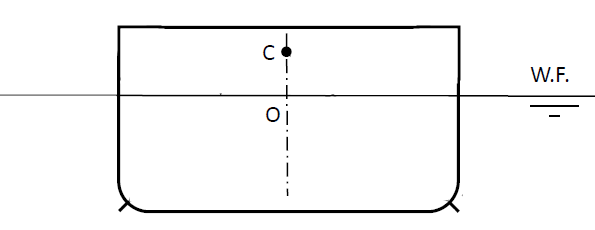
      To answer questions 1 and 2: the stability analysis takes all of the steady forces acting on a structure (buoyancy, weight, current, wind, mooring tensions, drift force due to waves etc), and then finds a position for the structure where all of those forces are in equilibrium. Therefore, when we start a time domain calculation from this position, we avoid a large initial acceleration on the structure because the net force is already zero.

      Naturally this only works if the steady forces acting in the time domain calculation are the same as they were in the stability analysis. So, the Aqwa editor allows you to define environment conditions in the stability analysis, and then right-click > Propagate them into any connected Hydrodynamic Response systems, to ensure that the environment is consistent between the analyses.

      To be clear, the stability analysis is not stepping through time - it is iterating towards a convergence where all of the forces are balanced. A time domain analysis linked to a stability analysis will still start at t = 0.

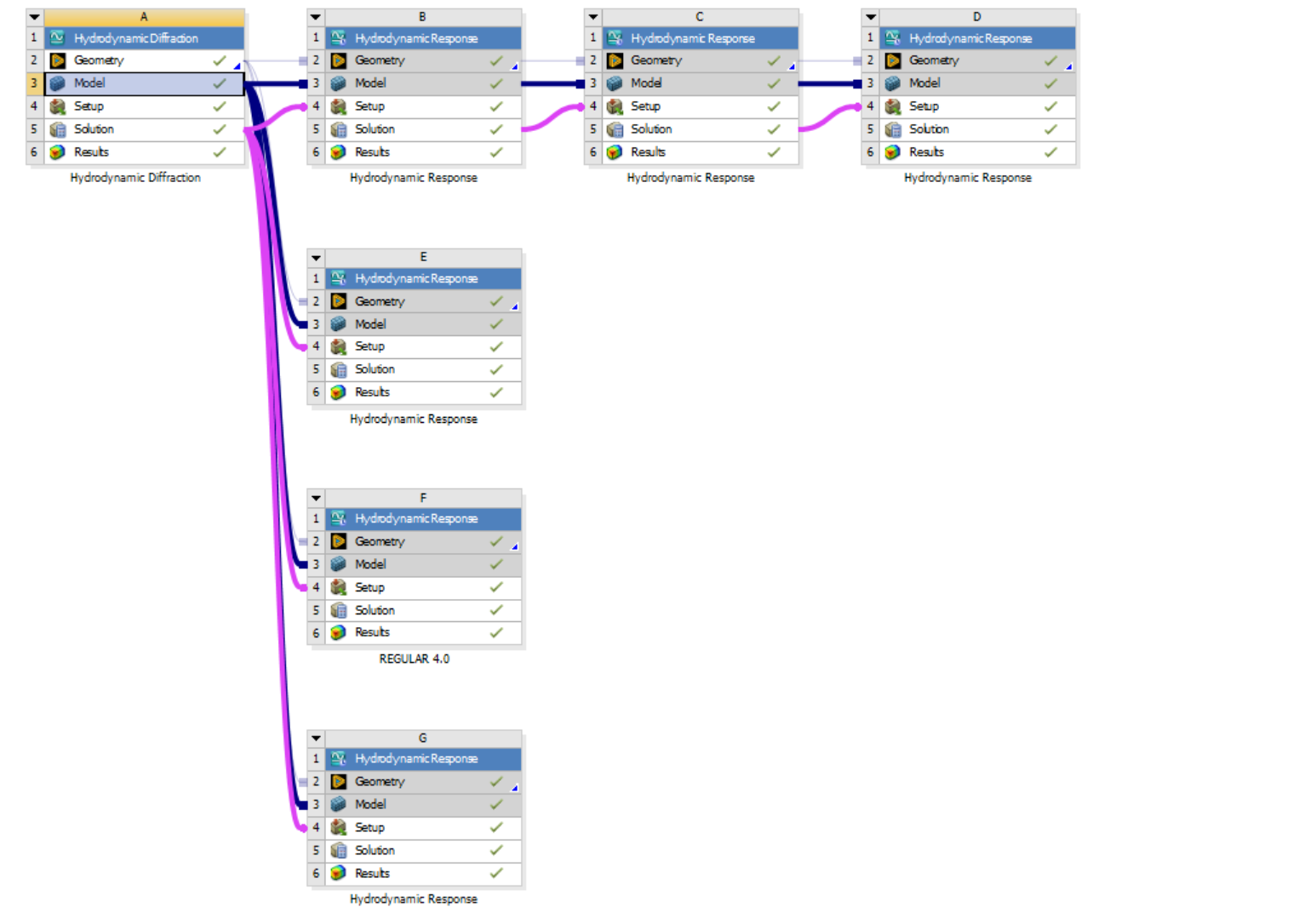
      Generally, if your time domain calculations do not include drift forces (i.e. the Analysis Type is set to 'Irregular Wave Response' or 'Regular Wave Response', or there is no Irregular Wave defined) and all of the other steady forces are the same (i.e. same current/wind definition, or no current/wind), then you can start each time domain analysis from the same stability analysis:

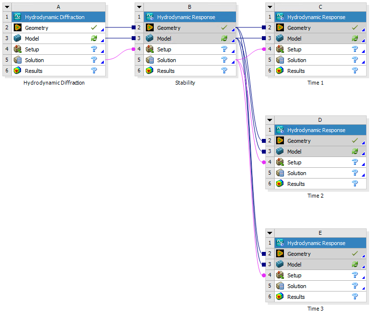
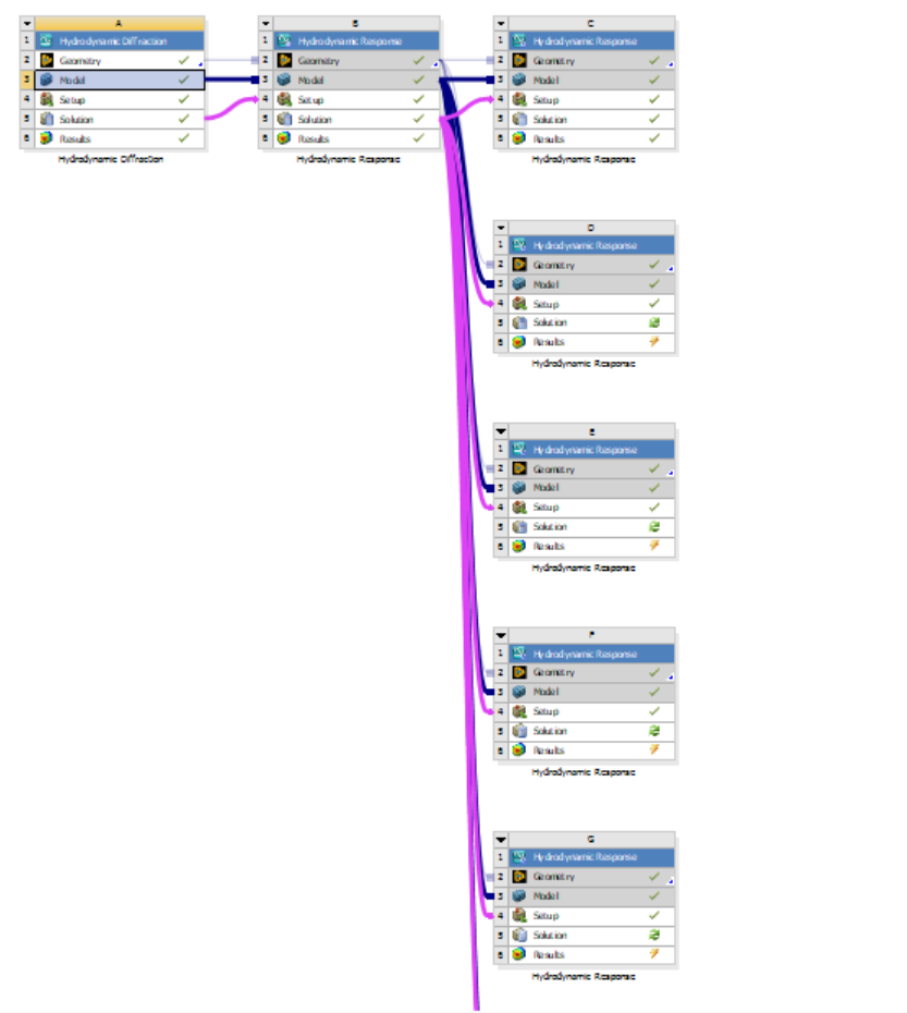
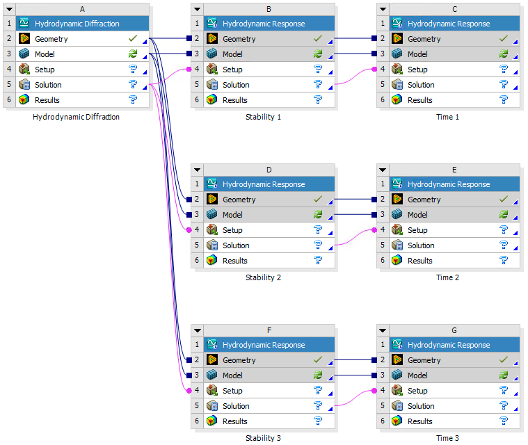
      If your time domain calculations do include drift forces (i.e. the Analysis Type is set to 'Irregular Wave Response with Slow Drift' or 'Slow Drift Only', and there is at least one Irregular Wave defined) or any of the other steady forces are different between analyses (i.e. different current/wind definitions), then you should start each time domain analysis from its own stability analysis:

      To answer your other questions:

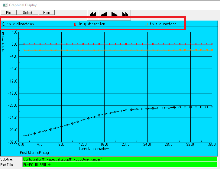
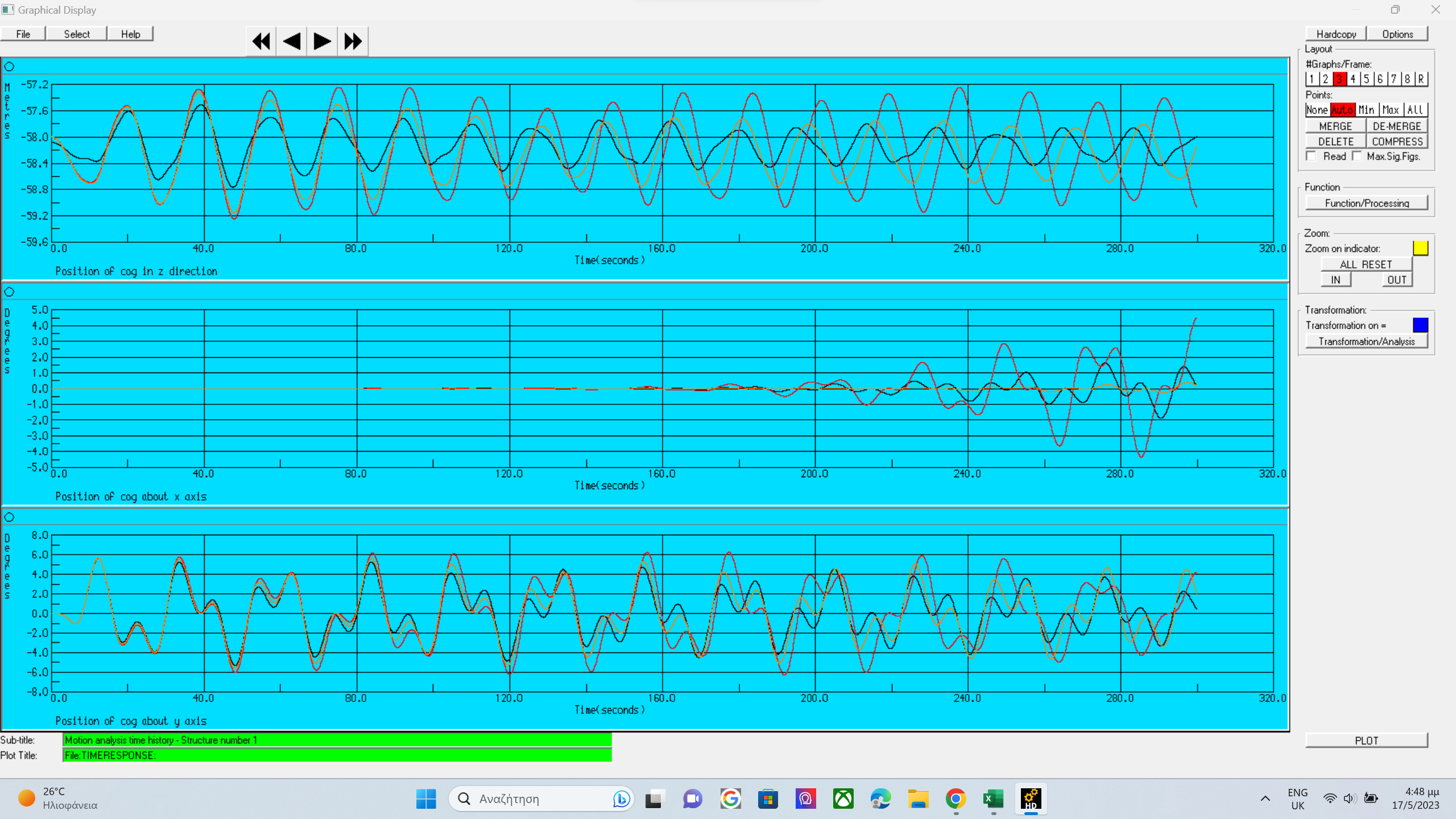
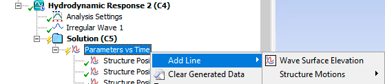
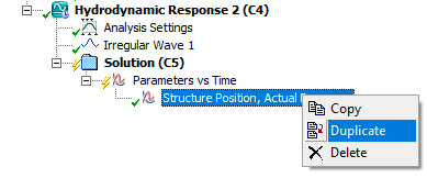
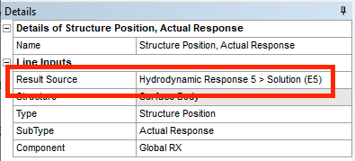
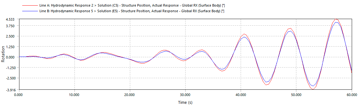
      3. I'm afraid AqwaGS does not have a capability to add a legend like this - you have to keep track of which dataset is which. However, I should mention that since Release 2021 R1, the Aqwa Workbench editor allows you to plot data from different systems within the same project:

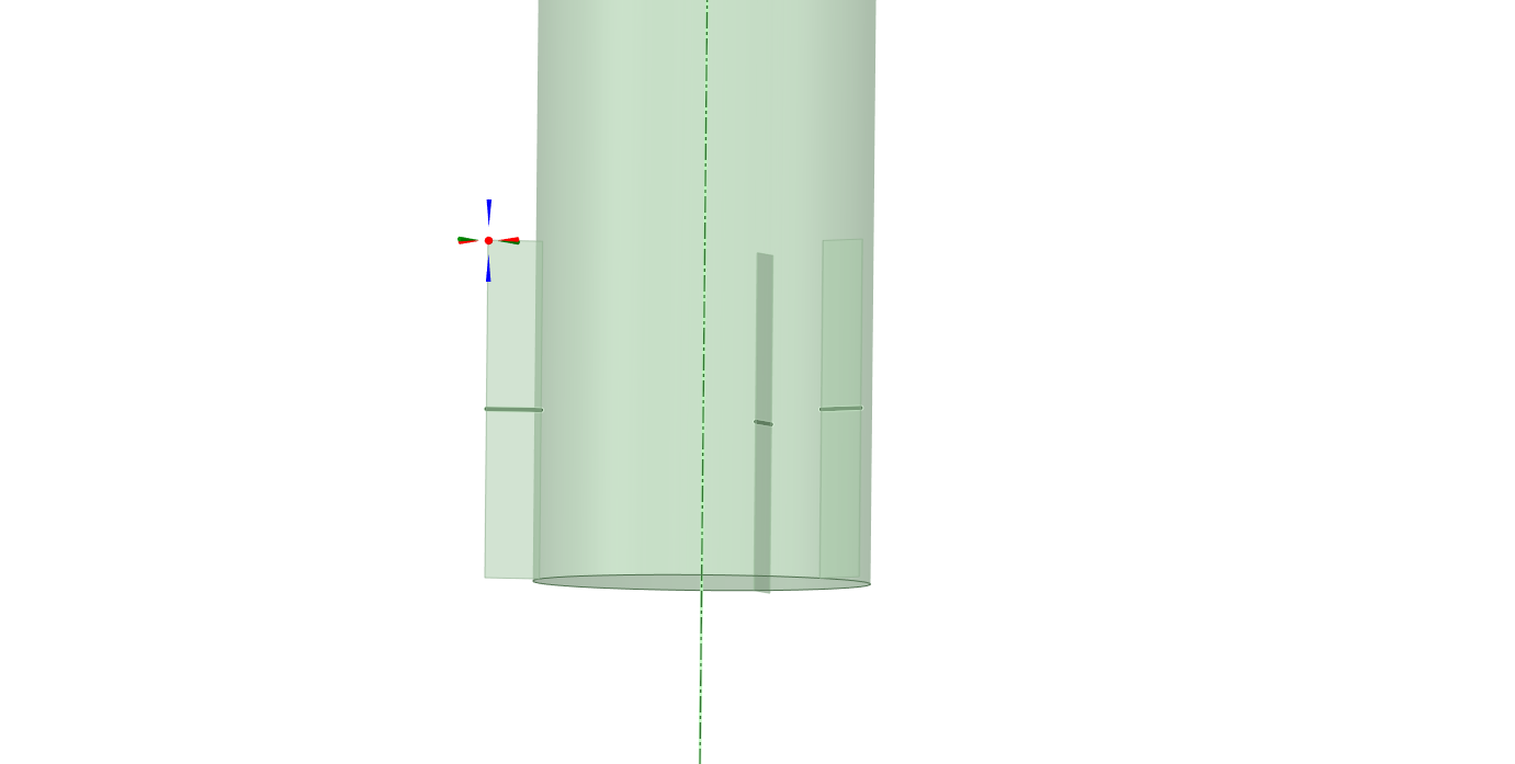
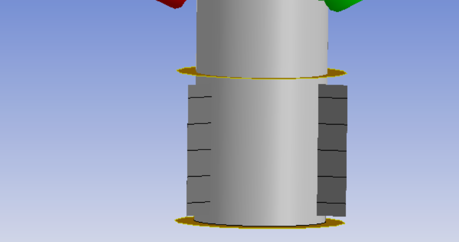
      4. I'm afraid there is no function to draw the strakes on the spar, either in Aqwa Workbench or AqwaGS.

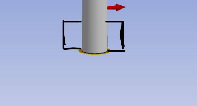
      5. The Morison discs are usually added at the ends of Morison tube elements, so the default added mass and drag coefficients assume that only one side of the disc is wetted. You might consider doubling the added mass and drag if both sides of the disc are immersed.

      I hope this helps!

      Cheers, Mike

    • pavlidisthrasuvoulos
      Subscriber


      Thanks again Mike!.As for the last part of the question,do you propose in case we have time response analyses with moorings,to have the linear connection stiffness matrices to ON?Do we have better solutions(i mean better response for our structure) in that case?And you mentioned that we can plot data from different systems within the same project.How can we do it??As i understand we can have many graphs for RX,RY,Z etc for different waves for example at one .

      Thanks again!!


    • Mike Pettit
      Ansys Employee

      Hi Greg,

      If you have defined some Cables under Connections, as well as a Connection Stiffness matrix, you should not turn on 'Include Linear Connection Stiffness Matrices'. If you do, in the Hydrodynamic Response analysis the global mooring stiffness will be twice the actual value, and your vessel response will be wrong.

      For plotting results from different systems: once you have added one graph result (e.g. right-click on Solution, Insert Result > Structure Motions > Structure Position > Actual Response), you can add a second line to the same graph axes by either:

      • right-clicking on the graph object and selecting Add Line

      • right-clicking on the result input object and selecting Duplicate

      If you have 2 time domain Hydrodynamic Response systems on the Project Schematic, then the graph input 'Result Source' option will allow you to choose which of those systems the result is plotted for.

      Cheers, Mike

    • pavlidisthrasuvoulos
      Subscriber

      Thank you for every help here Mike !!.Every question answered here

Viewing 24 reply threads
  • The topic ‘Ansys AQWA-How to add fins for damping at our offshore marine structure?’ is closed to new replies.