We have an exciting announcement about badges coming in May 2025. Until then, we will temporarily stop issuing new badges for course completions and certifications. However, all completions will be recorded and fulfilled after May 2025.
Electronics

Electronics

Topics related to HFSS, Maxwell, SIwave, Icepak, Electronics Enterprise and more.

How to model differential pair coupled to microstrip

    • Stefano R
      Subscriber

      Hello,

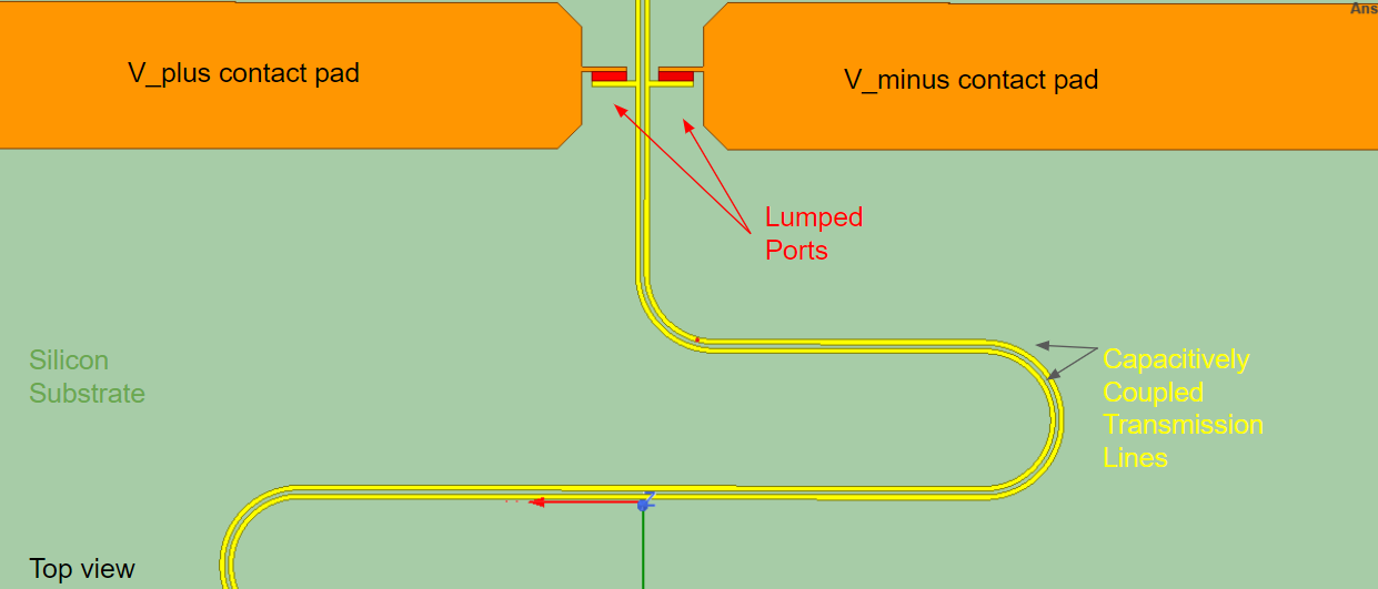
      I want to simulate a differential pair that is capacitively coupled to a microstrip pair. I have assigned PerfE boundaries to each trace and pad element in yellow. There is no GND plane in this model, the wires act as reference and do not receive direct excitation. I am confused about how to create a port for this model. Any suggestions?

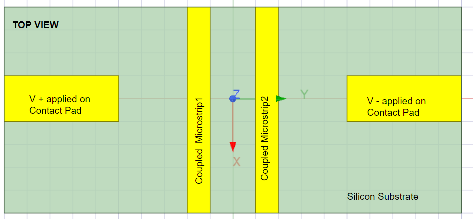
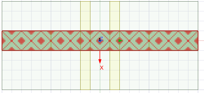
      I tried making a rectangle over the contact pads and assigning a wave port as shown below. This let me define the diff pair and set the wires as reference. This passed validation check but gives an error on analyzing "Too few conductors were found on port 1. There should be one conductor for each terminal, with one additional reference conductor. Unintentional contact between conductors may cause this error..".

      I instead added two lumped ports and edited the sources to be 180 degrees out of phase with respect to each other. This does not give errors and can give a solution, but is it physically correct?


      image.png


    • Faezeh Ladani
      Ansys Employee

      Hi Srocca,

      There are a number of open examples in the HFSS student version which you can install and explore. Go to File>Open Examples...>HFSS>Transmission Lines... Also, explore some other examples in RF Microwave and Filter Folders. These examples will help you learn more about how to assign waveport and lumped ports. You may explore Lumped port excitations as well. 

      In general, also make sure that whatever pads or planes you have as ground (or reference) are all connected. 

      If you have access to customer portal, file a support ticket and one of our engineers will work 1-1 with you on that. 


    • Stefano R
      Subscriber

      Faezeh,

      Thank you for the response. The two reference transmission lines are not physically connected because we are investigating the capacitive coupling between the lines. The contact pads are also not physically connected to the transmission lines due to the same reason. Do you think this is modeled well as shown in the last image?

    • Stefano R
      Subscriber

      I read the example on coupled transmission lines. My concern is that my differential paid and reference lines are on the same top plane. This is confusing me as to how to create a port. 

      Here is my model with the imported geometry. Where should I make the ports?

Viewing 3 reply threads
  • The topic ‘How to model differential pair coupled to microstrip’ is closed to new replies.