-
-
March 28, 2023 at 3:37 pm
Miguel Gonzalez
SubscriberHi allÂ
I did a simulation an inductive link(Rx and Tx same size) in HFSS and Maxwell(Eddy current) , I got a close inducance values between both simulations(Maxwell L=1.28uH)(HFSS L=1.22uH). The coupling coeffiencient in HFSS was 0.067 while in MAXWELL(EDDY CURRENT) was 0.0708.But the resistance values are not matching in HFSS I got 1.21 ohm while in MAXWELL(EDDY CURRENT) I am getting 0.547 ohm.
I would like to know why is the difference?. I calculate the resistance in hfss with re(Z(1,1)).
-
April 11, 2023 at 2:43 pm
Praneeth
Bbp_moderatorHi Miguel,
Thank you for reaching out and your patience is much appreciated.
Ansys Q3D is the best tool for this scenario. It can calculate the resistance and inductance of the coil. Here is the link to Ansys Innovation course on using Q3D - Intro to Ansys Q3D | Ansys Innovation Course.
But if you want to compare the results of HFSS and Maxwell simulation then you need to make sure that the simulation model is set up identically for getting similar results. Kindly share snapshots of your HFSS model and setup. It is observed that the difference between inductance calculations is reduced as compared to your previous post. Please let us know what modifications are done to serve you better.
The Maxwell part of the query will be addressed by the concerned person shortly.
Best regards,
Praneeth. -
April 11, 2023 at 3:47 pm
Miguel Gonzalez
SubscriberHi Praneeth
Thank you for your answer.
I got the a closer inductacnce value when I increase the size of the radiation boundary. I read that the boundary should be at least 1/4 of the wavelength. The woorking frequency is 13.56 MHz , the wavelenght is 22m , which is 5m ,so I drew a box with 8m high, long and wide for the boundary.
I used lumped port with 50 ohm impedance
Thanks,
Miguel
Â
-
April 13, 2023 at 12:29 pm
Navya Chode
Forum ModeratorHi Miguel,
On Maxwell, I have gone through your previous question as well about Eddy current resistance.Â
Eddy current solver gives you the resistance that is seen when using the steady AC current. I am not sure if you can call it AC resistance.
Regarding the difference in your results. I am not sure why it is happening. can you check the results by increasing the region size in steps?
If you have access to Ansys customer support please submit a service request to have this verified.
Regards,
Navya
Â
Â
-
- The topic ‘
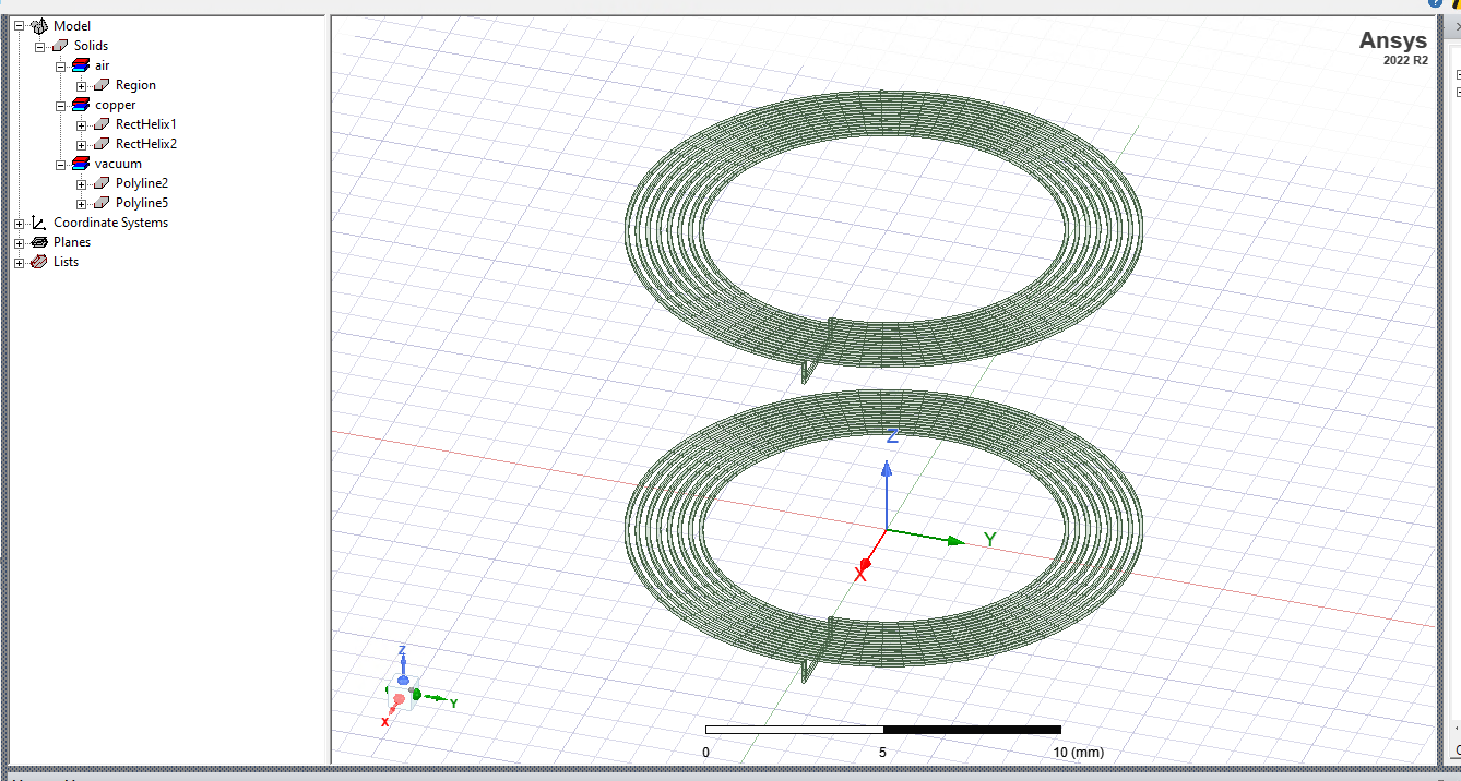
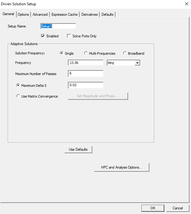
Resistance difference between HFSS and MAXWELL(EDDY CURRENT)’ is closed to new replies.
-
3712
-
1313
-
1163
-
1090
-
1014
© 2025 Copyright ANSYS, Inc. All rights reserved.