-
-
March 16, 2023 at 8:38 am
Naeel D
SubscriberHello all,
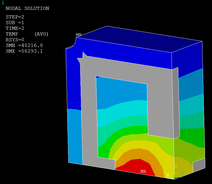
I have attempted to simulate additive manufacturing using ANSYS APDL. I have already applied an element type of SOLID278 with relevant material properties for aluminum 7075. I have also used 'Mapped Meshing' due to my design parameters. In addition to this, I have used the 'Element Birth and Death Technique' with a 'DO* LOOP' to simulate the additive manufacturing of 'Laser Cladding'. However, after running my PYANSYS code, I am running into this error where physical gaps are visible once the simulation is complete (shown in the image below). I would appreciate the solution to this cause.
The following code below is my code used for the full process in ANSYS APDL:
!----------------!Pre-processing----------------/PREP7!*ET,1,SOLID70 !Thermal 3D element!----------------!Defining Material Properties----------------!*/UNIT,SIMPTEMP,,,,,,,,MPTEMP,1,0MPDATA,EX,1,,71.7e09MPDATA,PRXY,1,,0.32MPTEMP,,,,,,,,MPTEMP,1,0MPDATA,KXX,1,,130MPTEMP,,,,,,,,MPTEMP,1,0MPDATA,C,1,,960MPTEMP,,,,,,,,MPTEMP,1,0MPDATA,DENS,1,,2810!----------------!Geometry----------------/PREP7K, ,0,0,0, !Modelling with Keypoints to create geometryK, ,0.004,0,0,K, ,0.005,0,0,K, ,0.005,0,0.002,K, ,0.004,0,0.002,K, ,0,0,0.002,K, ,0,0.004,0,K, ,0.004,0.004,0,K, ,0.005,0.004,0,K, ,0.005,0.004,0.002,K, ,0.004,0.004,0.002,K, ,0,0.004,0.002,K, ,0,0.005,0,K, ,0.004,0.005,0,K, ,0.005,0.005,0,K, ,0.005,0.005,0.002,K, ,0.004,0.005,0.002,K, ,0,0.005,0.002,!*CYL4,0.005,0.005,0.0005, , , ,0.002 !Create CyclinderlplotKL,7,0.5, ,KL,2,0.5, ,!*/REPLO !Create Volumes from KeypointsV, 1, 2, 5, 6, 7, 8, 11, 12V, 2, 3, 4, 5, 8, 9, 10, 11V, 7, 8, 11, 12, 13, 14, 17, 18V, 14, 21, 25, 17, 8, 28, 27, 11V, 8, 28, 27, 11, 9, 19, 26, 10!*FLST,2,2,6,ORDE,2 !Substract Cyclinder from Main VolumeFITEM,2,5FITEM,2,-6VSBV,P51X, 1!----------------!Optimised Mesh (Mesh Size 0.4mm)----------------lplotFLST,5,41,4,ORDE,10FITEM,5,9FITEM,5,11FITEM,5,-40FITEM,5,42FITEM,5,-43FITEM,5,45FITEM,5,47FITEM,5,-48FITEM,5,50FITEM,5,-54CM,_Y,LINELSEL, , , ,P51XCM,_Y1,LINECMSEL,,_Y!*LESIZE,_Y1,0.0004, , , , , , ,1!*!----------------!Creating the Mesh (0.4mm)----------------FLST,5,5,6,ORDE,4FITEM,5,2FITEM,5,-4FITEM,5,7FITEM,5,-8CM,_Y,VOLUVSEL, , , ,P51XCM,_Y1,VOLUCHKMSH,'VOLU'CMSEL,S,_Y!*!*VCLEAR,_Y1VMESH,_Y1!*CMDELE,_YCMDELE,_Y1CMDELE,_Y2!*!----------------!Solutions-Settings----------------/SOLTUNIF,293, !Uniform temperatureTREF,293, !Reference temperatureKBC,0 !Ramped loadingNEQIT,100 !No. of iteration!*ANTYPE,4 !Define model Transient Analysis!*TRNOPT,FULL !Define Solution MethodLUMPM,0 !Use of 'Lumped Mass approx.'!*NROPT,FULL !Specify Newton-Raphson as Full Transient AnalysisTIME,1 !End of Time Step!----------------!Kill all ELEMENTS----------------!*FLST,5,114,1,ORDE,2 !Select all NODESFITEM,5,1FITEM,5,-114NSEL,S, , ,P51XESLN,S !Select all ELEMENTS attached to those NODES/GRAPHICS,FULL !Turn Off POWERGRAPHICSEKILL,ALL !Deactivate all ELEMENTSESEL,S,LIVE !To confirm success of EKILL command: Select all 'Live ELEMENTS'/REPLO!----------------!DO LOOP COMMAND----------------*set,user_time,0!*do,variable_z,0,0.002,0.001!*do,variable_y,0,0.005,0.0012*do,variable_x,0,0.0012,0.0012NSEL,S,LOC,X,1*variable_x,0.0012+variable_xNSEL,R,LOC,Y,1*variable_y,0.0012+variable_yNSEL,R,LOC,Z,1*variable_z,*0.001+variable_zESLN,SEALIVE,ALL !Re-Activate Selected NODESSFE,ALL, ,HFLUX, ,10e05!DELTIM,0.1,0,0 !Time step size, 0.1 suser_time=user_time+1TIME,user_time !Total time, 1 sAllSEL,ALLSOLVESFEDELE,all,all,all !Removing surface element load/GRAPIHCS,POWER !Turn On POWERGRAPHICSesel,s,liveeplot*enddo!*enddo!*enddoThank you,
Naeel D
-
March 22, 2023 at 12:41 pm
John Doyle
Ansys EmployeeSeems like an error in your select logic. What happens if you select all the elements before the last plot (as a test)?
-
March 22, 2023 at 3:02 pm
-
-
March 22, 2023 at 6:34 pm
John Doyle
Ansys EmployeeI think it still comes down to select logic. The gray elements are what remain killed.
-
May 30, 2023 at 2:17 pm
Mike Rife
Ansys EmployeeHi Naeel
Check this code block as there are more than 114 nodes in the model. Instead of using picking commands, maybe change to nsel,all and esel,all etc
!----------------!Kill all ELEMENTS----------------!*FLST,5,114,1,ORDE,2 !Select all NODESFITEM,5,1FITEM,5,-114NSEL,S, , ,P51XESLN,S !Select all ELEMENTS attached to those NODES/GRAPHICS,FULL !Turn Off POWERGRAPHICSEKILL,ALL !Deactivate all ELEMENTSESEL,S,LIVE !To confirm success of EKILL command: Select all 'Live ELEMENTS'/REPLO
-
- The topic ‘Error in Additive simulation via ANSYS APDL’ is closed to new replies.


-
4683
-
1565
-
1386
-
1242
-
1021

© 2025 Copyright ANSYS, Inc. All rights reserved.


