Hello seffa
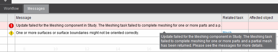
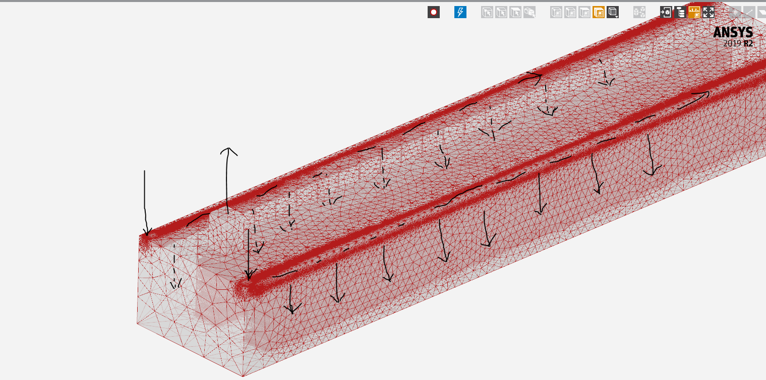
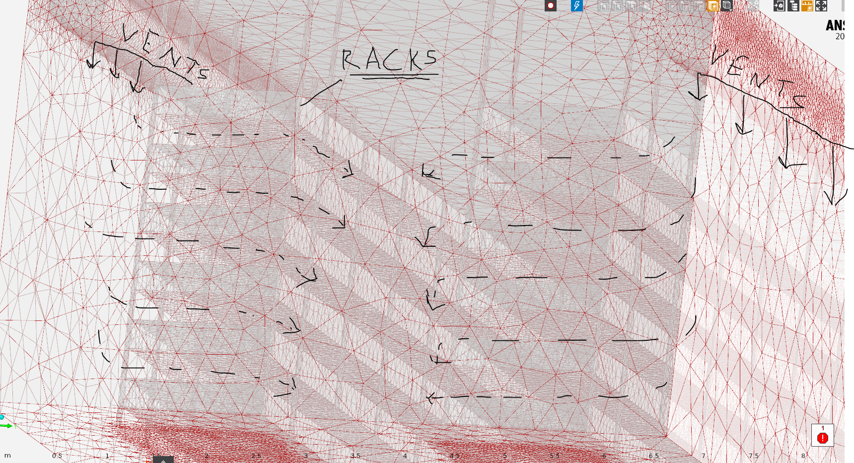
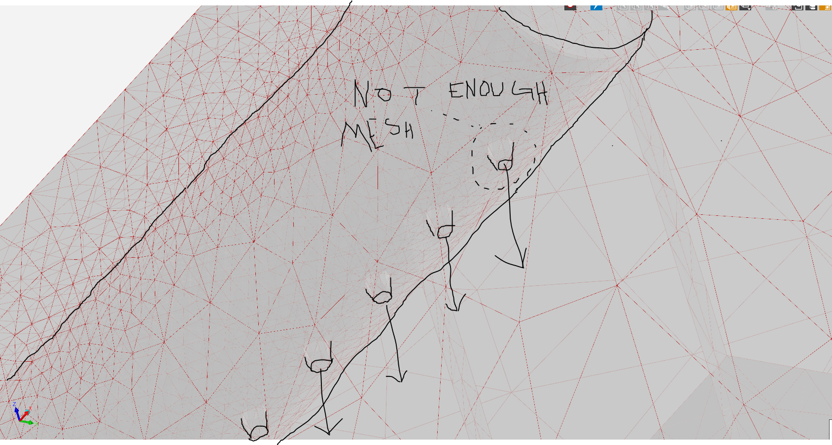
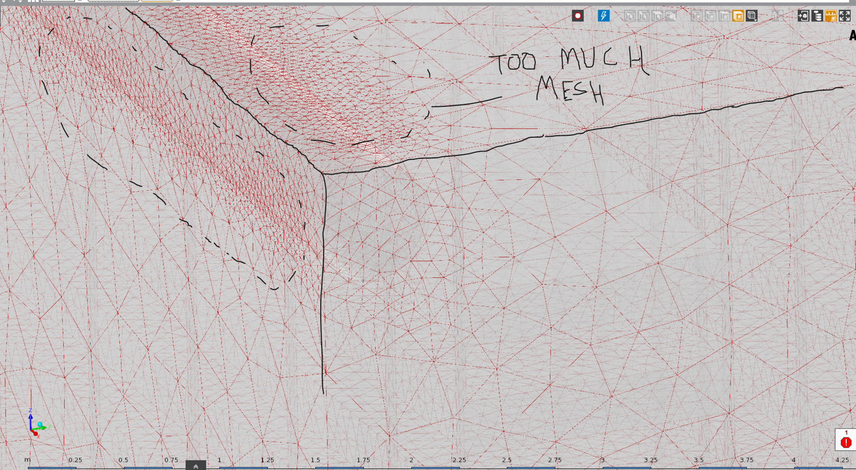
Though the geometry details cannot be clearly understood from the images that you uploaded, it appears that the model contains lots of small holes and thin regions. Below are some suggestions to help generate a successful mesh:
1. Before proceeding for mesh generation, please check the geometry in Geometry Editor (or SpaceClaim) for any unwanted small entities which may cause problems in meshing and/or create unnecessary mesh refinement. Tools like "Small Faces", "Split Edges" can help to locate the small entities in the model and if they are not important from simulation point of view, you can remove them.
It is also a good practice to review the geometry by looking at the sectional views in different directions to get an idea of the internal geometry features, regions which can be further simplified and so on. Sometimes, unwanted gaps or thin regions are generated due to geometry misalignments and so on which can be located in such sectional views. Such views also give you a better idea about the level of mesh refinement needed. For example, for a thin region, you can measure the thickness of the region which will help you to specify appropriate proximity sizing to generate a reasonable refined mesh in the thin region.
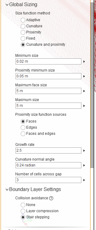
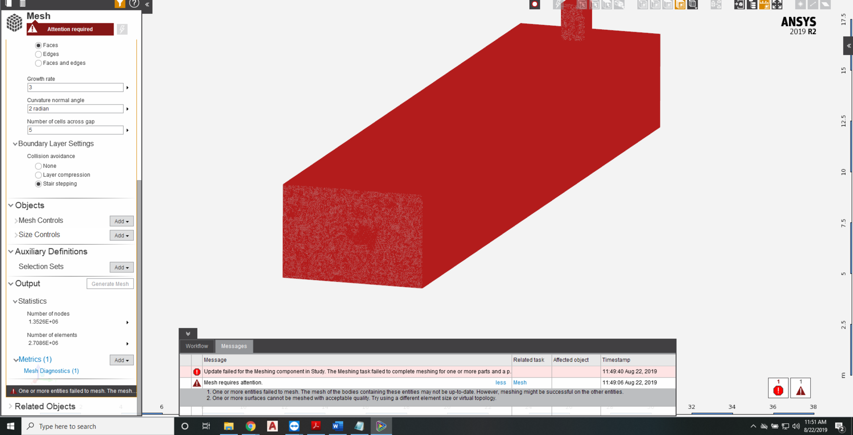
2. While generating mesh, it is important to correctly specify the mesh parameters for generating a good mesh which won't create problems while solving. In one of the latest images shared by you, I can see mesh parameters like Growth Rate =2, Curvature normal angle = 2 radians and, Number of cells across gap = 5. The growth rate value is on a very higher side and such value is not recommended for CFD problems. You may want to reduce it to 1.2 or 1.4. The curvature normal angle is also too coarse which you may want to reduce it to 18 deg or 24 deg. Also, you can go with 3 cells across gaps in proximity regions which will help to reduce the mesh count and generate a good mesh in thin regions. The min size and proximity min size also need to be appropriately defined so that the intended features are properly captured in meshing.