General Mechanical

General Mechanical

Topics related to Mechanical Enterprise, Motion, Additive Print and more.

Falling under the force of gravity into a transient

    • javat33489
      Subscriber

      Hello. I want to simulate the movement of one part under the force of gravity down, but it flies away and does not see the contact in the other. Flat task. In contact, I tried everything, set the radius, changed the type of contact. The part as if does not see the contact and flies through.

      What could be the problem? Thank you.

    • Rahul Kumbhar
      Ansys Employee

      Under the connection, insert the contact tool and check its initial status. This contact status should be close.

    • dlooman
      Ansys Employee

      Maybe do an initial step where you hold the bodies in place to establish the initial contact.

    • mjmiddle
      Ansys Employee

      The time step needs to be small enough so that contacts are within the pinball radius during a substep. Otherwise it can go from far outside contact pinball above to far outside pinball below in one time step and is never within the pinball radius to detect contact. You can increase the contact pinball, but usually you need to make time stepping low enough. There is a contact setting "predict for impact" to help with this, and you can set time stepping in the analysis settings. Also, be aware that transient usually needs some damping, either global or local. If contacts impact, they can rebound with even more energy due to the contact stiffness behavior and then the next near-contact detection can be moving faster and fly through. This behavior is noticable when viewing the time history. Lowering contact stiffness can recduce that behavior but the analysis really needs damping to prevent it.

      • javat33489
        Subscriber

        Thanks for answers! Indeed, under the influence of gravity, the part jumps strongly:

        animation:


        contact

    • peteroznewman
      Subscriber

      Hello Javat,

      If the part is in free fall, meaning that the only force acting on the part is gravity, the correct way to model this is to calculate the impact velocity from the distance of the fall, and assemble the parts so that the falling part is positioned at the point of contact. The falling part is given the Initial Condition of a downward velocity equal to the impact velocity. That means that at time=0, the contact is already closed and ready to begin decelerating the part.

      Calculating the impact velocity from the drop height is a simple physics equation, or you can use an online calculator.

      You still have to turn on Auto Time Stepping and make the Initial Time Step a small number like 1e-4 s, the Minimum Time Step 1e-6 s and the Maximum Time Step 1e-3 s.

      • javat33489
        Subscriber

        I would like to solve with the help of gravity, the tasks are different, the distances are different. It would be more convenient with the help of gravity.

    • mjmiddle
      Ansys Employee

      Try some global damping under "Analysis Settings > Damping Controls > Stiffness Coefficient" = 0.001.

      If you want some local damping, you can create a spring between the bodies with zero stiffness coefficient, and only damping coefficient specified. Or damping can be specified on the material.

      • javat33489
        Subscriber

        thanks, I'll try!

    • peteroznewman
      Subscriber

      "I would like to solve with the help of gravity, the tasks are different, the distances are different. It would be more convenient with the help of gravity."

      I think it is more convenient to always have the geometry in contact, and only change the impact velocity for different tasks. It is less convenient to move the geometry to different drop heights for different tasks. In addition, a lot of computation time is wasted using gravity and time to wait for the part to reach the point of contact. The drop phase gives no useful information, all the useful information is after impact.

      • javat33489
        Subscriber

        Yes! You're right, it's much better that way. No need to wait for bounces and saves time. But for some reason it doesn't work for me. I made a speed on the site, and attached it to the simulation. The part is very strongly deformed, although very strong steel is used:


        I also tried using the time from the site, but it didn't help:

        I also have a question. If I need to simulate 50 such impacts, how can I enable it in the program?

    • peter.newman
      Subscriber

      "If I need to simulate 50 such impacts, how can I enable it in the program?"

      That is actually really difficult to do. See this thread.

      /forum/forums/topic/double-drop-test-for-molded-pulp-packaging/

    • peter.newman
      Subscriber

      Javat,

      It looks like you have applied a Velocity Boundary Condition. This is a mistake. It means the part shall always travel at that velocity no matter how much force is required and the longer the end time, the larger the distance it will travel.

      Use an Initial Condition of Velocity. This is very different than a Boundary Condition. It is only true at t=0 and after that, the solution proceeds and the kinetic energy in the moving part is converted into elastic and plastic work, slowing the initial velocity down to zero at some small displacement.

      • javat33489
        Subscriber


        Oh yeah, that’s my mistake! Thank you!

        I made the initial speed, now everything works but wrong.

        I think dumping is not working properly.

        The part bounces heavily without dumping. If I set the dumping factor to 0.02 (for example), then it is noticeable that the load goes on for the first fractions of a second, then disappears and freezes until the end of the calculation.

        I don’t understand how to deal with it.

        I have attached the task file:

        ARCHIVE


    • butres ali
      Subscriber

      I'd want to tackle this problem using gravity, however the challenges and the requirements are all different. Having the assistance of gravity would make things much easier to manage. /forum/forums/topic/double-drop-test-for-molded-pulp-packaging/color by number

      • javat33489
        Subscriber

        I saw this post, it won't help. I have other questions.

    • javat33489
      Subscriber

      HELP

    • peteroznewman
      Subscriber

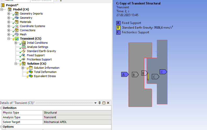
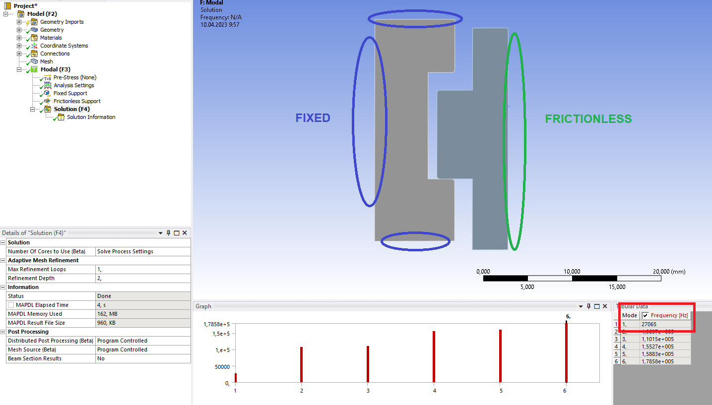
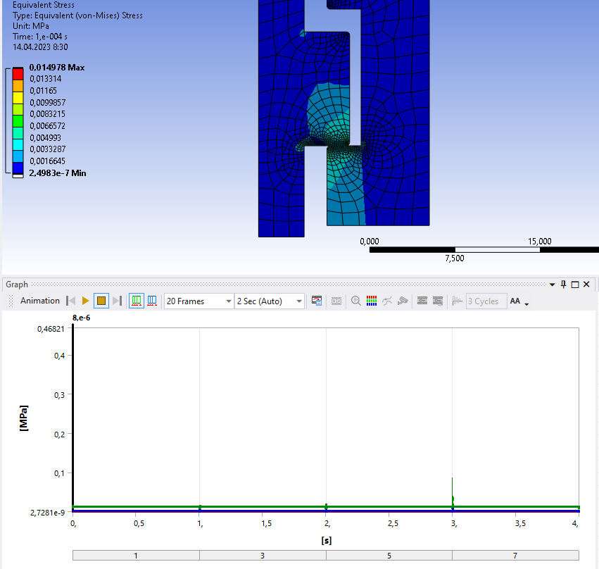
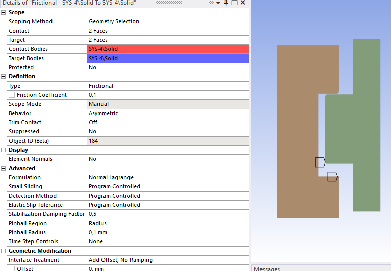
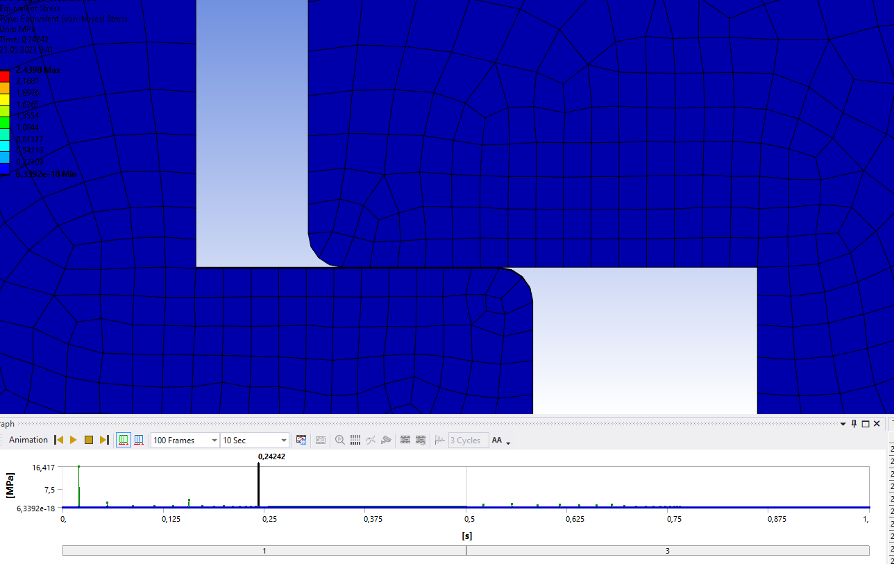
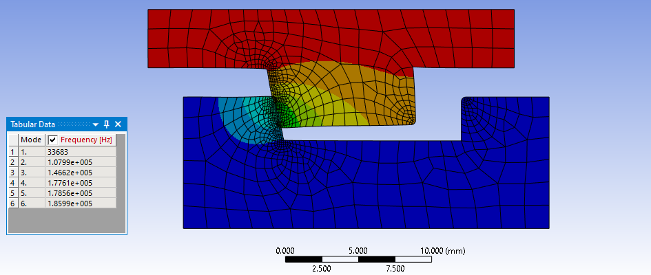
      It is useful to know the first mode from a Modal analysis, which is 33683 Hz when the part is in contact.

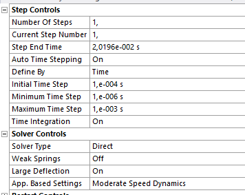
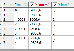
      That helps you to calculate a time increment and damping. The period for 33683 Hz is about 3e-5 s, which is for a full cycle. You want at least 20 time points over that period, so 1.5e-6 is a good Initial and Maximum Time Increment for Transient Structural. I used the values below.

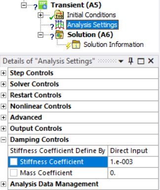
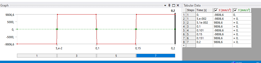
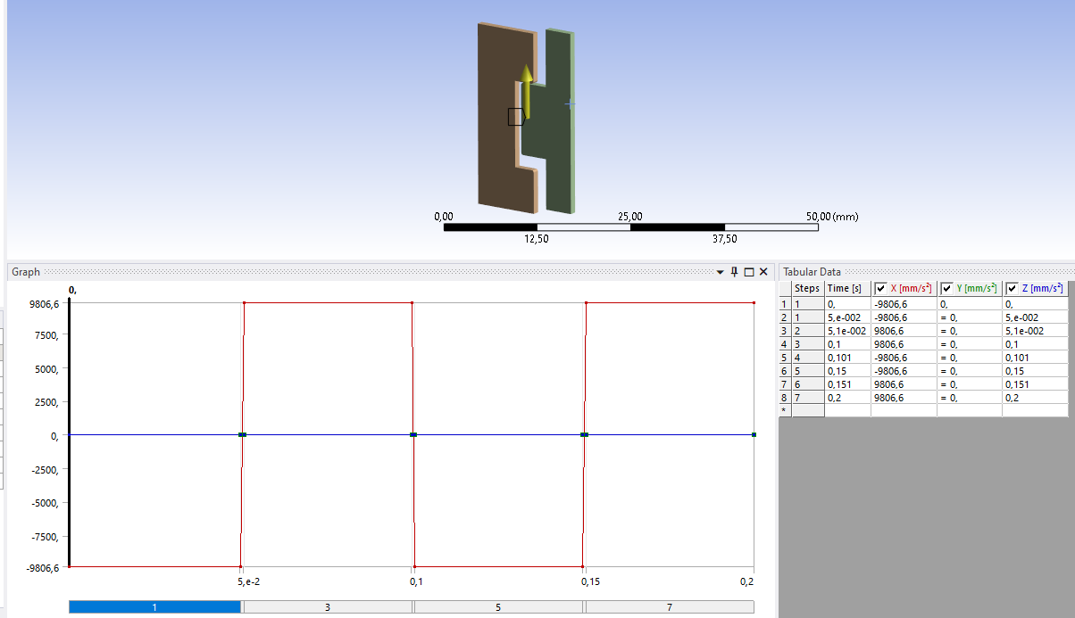
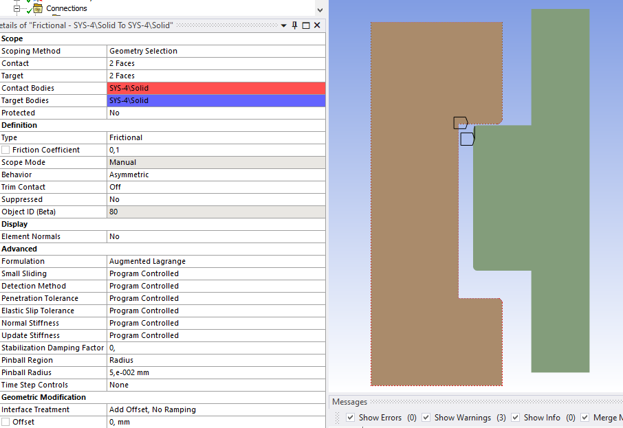
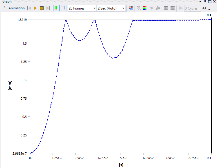
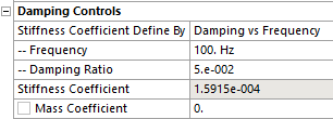
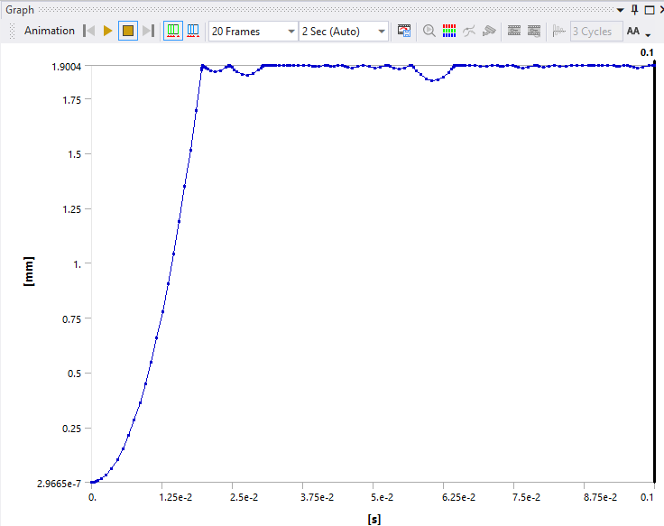
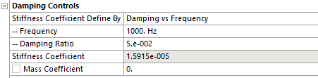
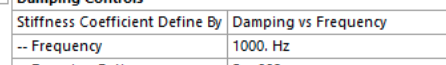
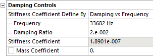
      Use a Damping by Frequency input of 2% at this frequency.

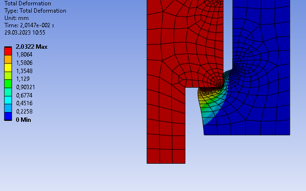
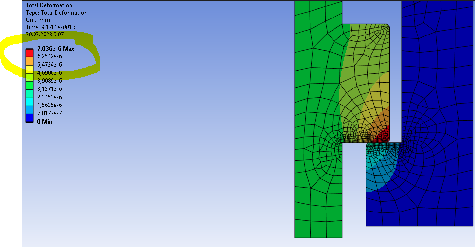
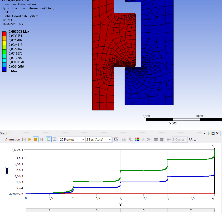
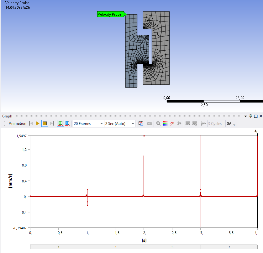
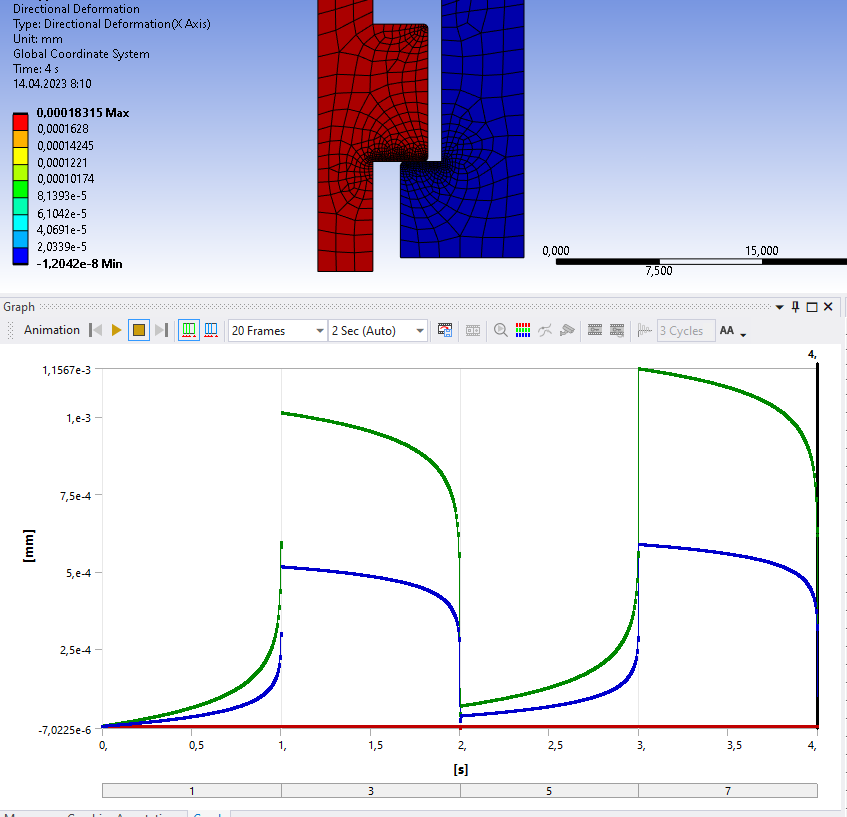
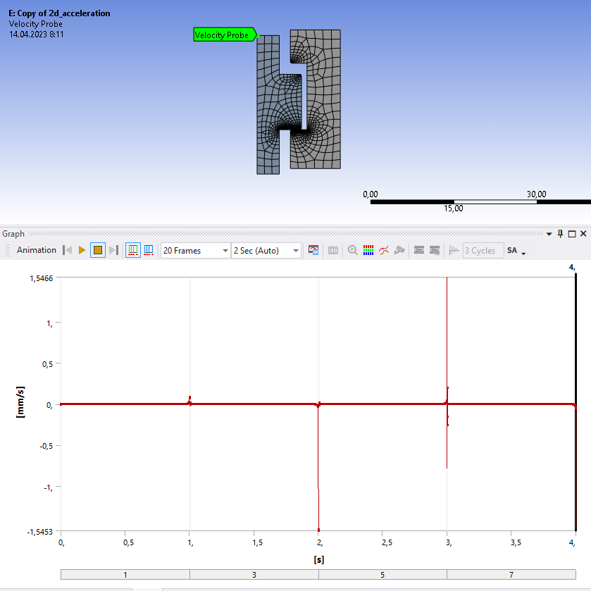
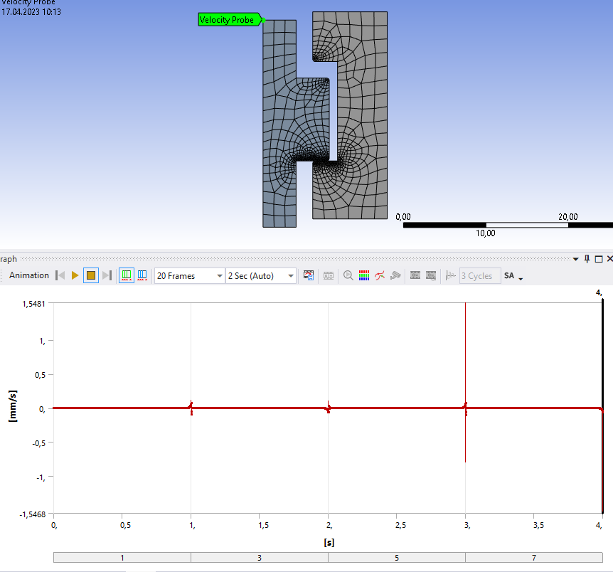
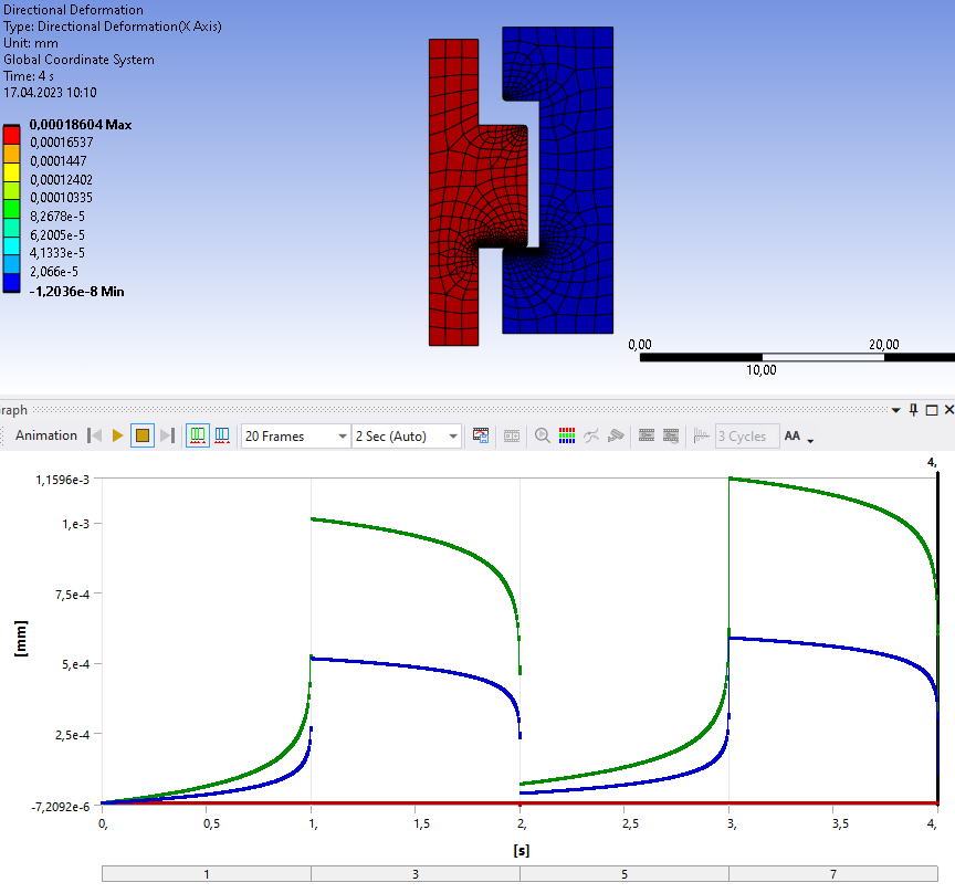
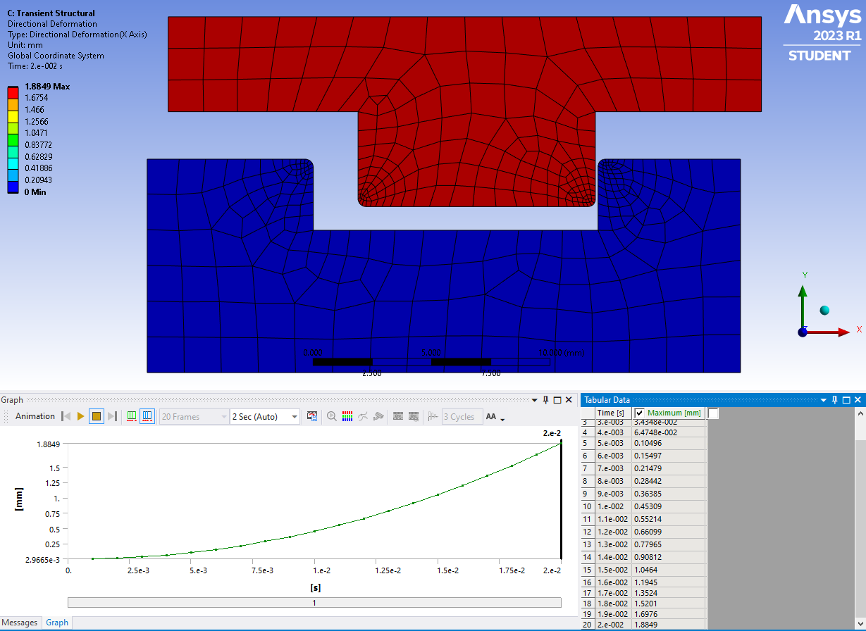
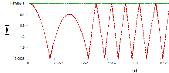
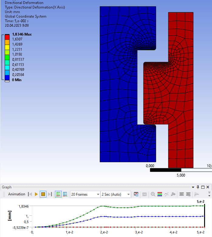
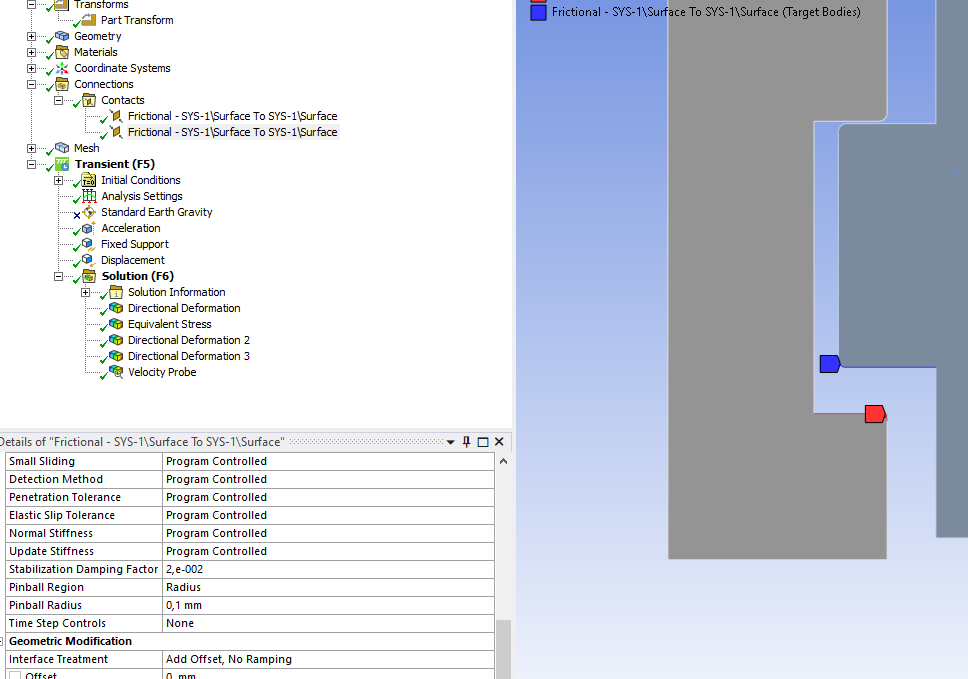
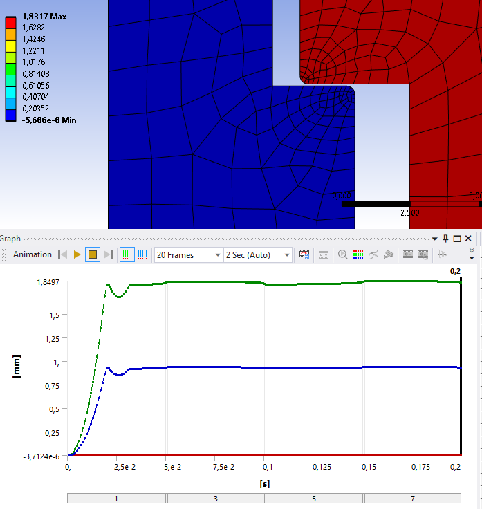
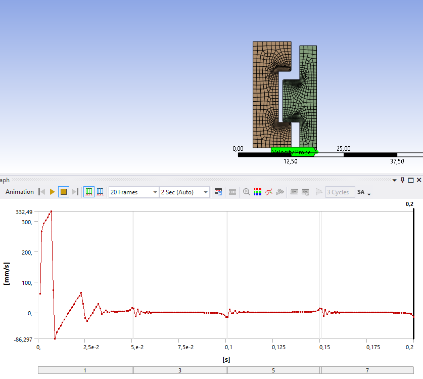
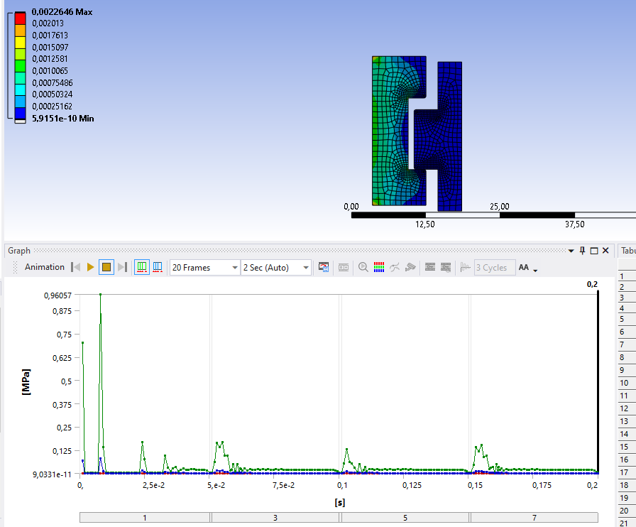
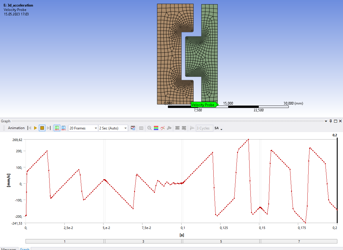
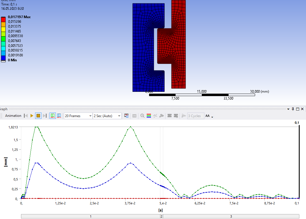
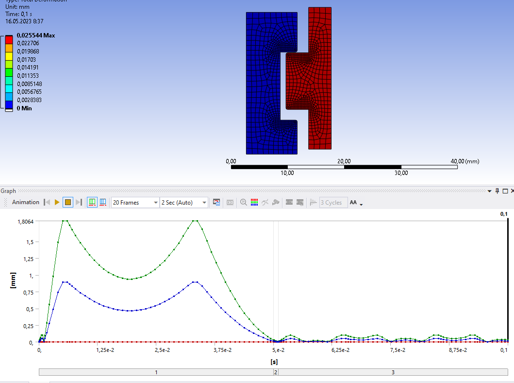
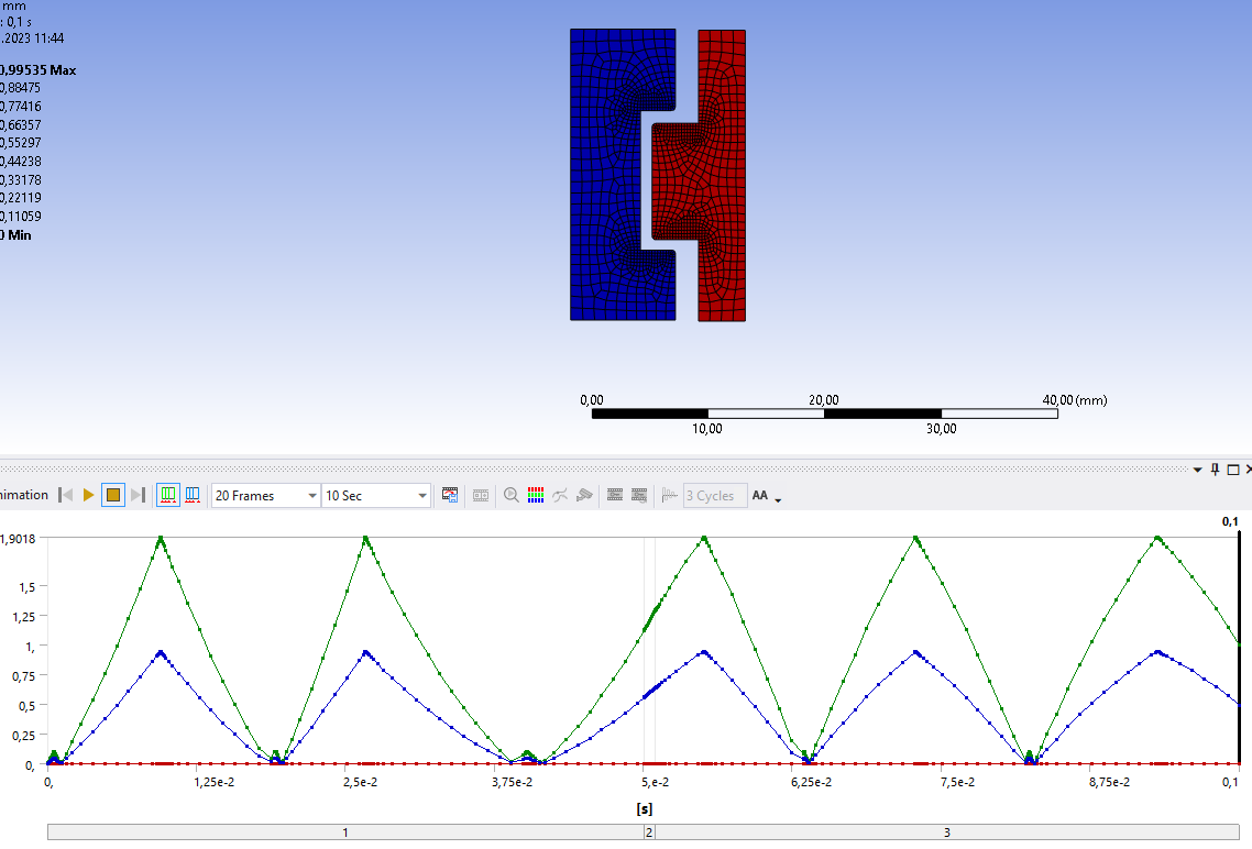
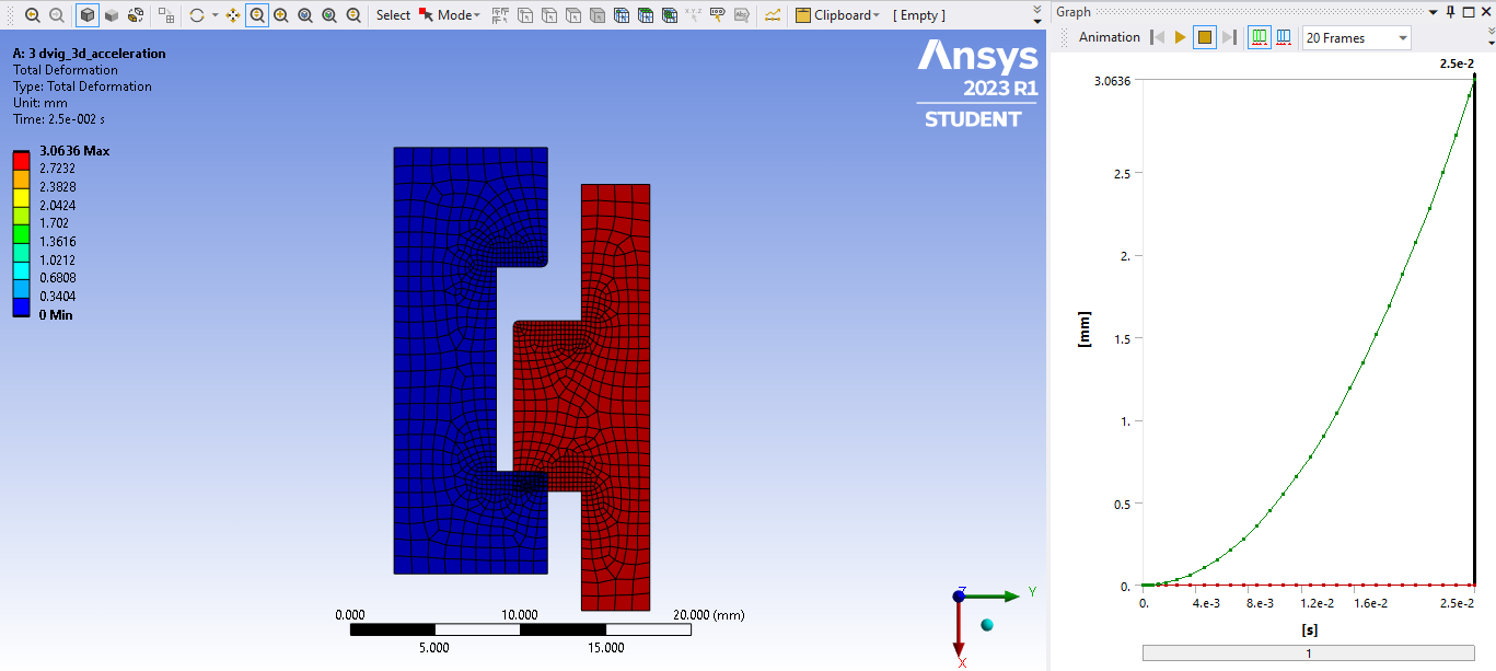
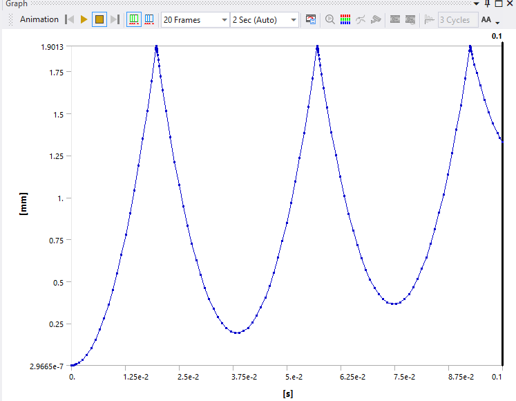
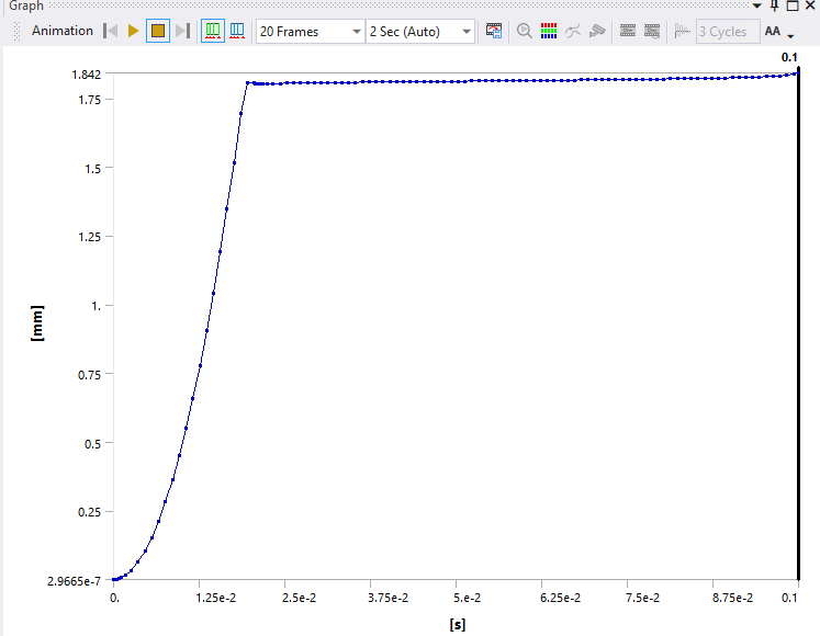
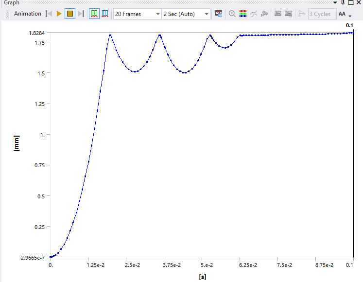
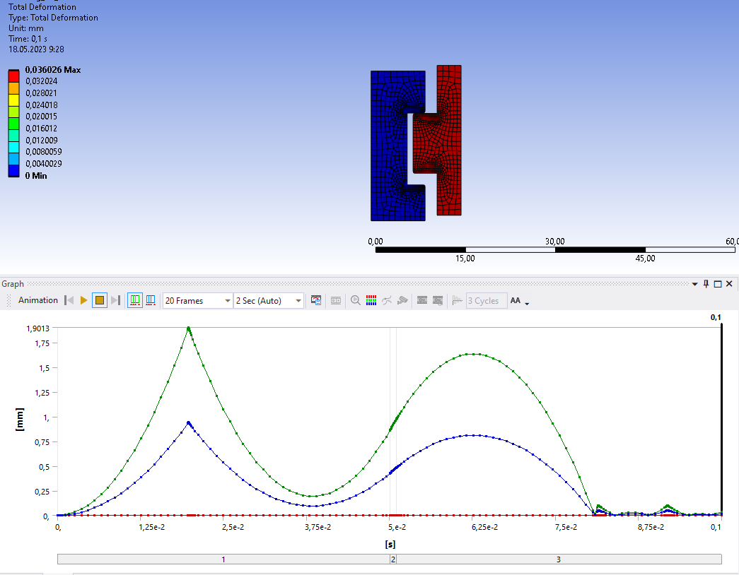
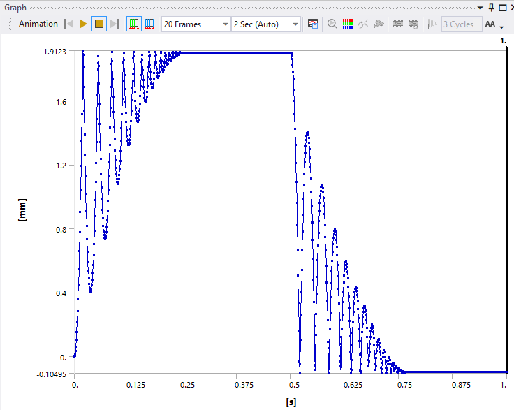
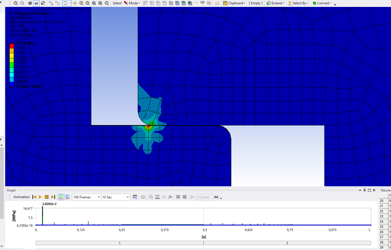
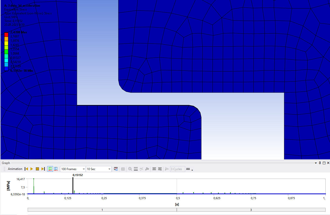
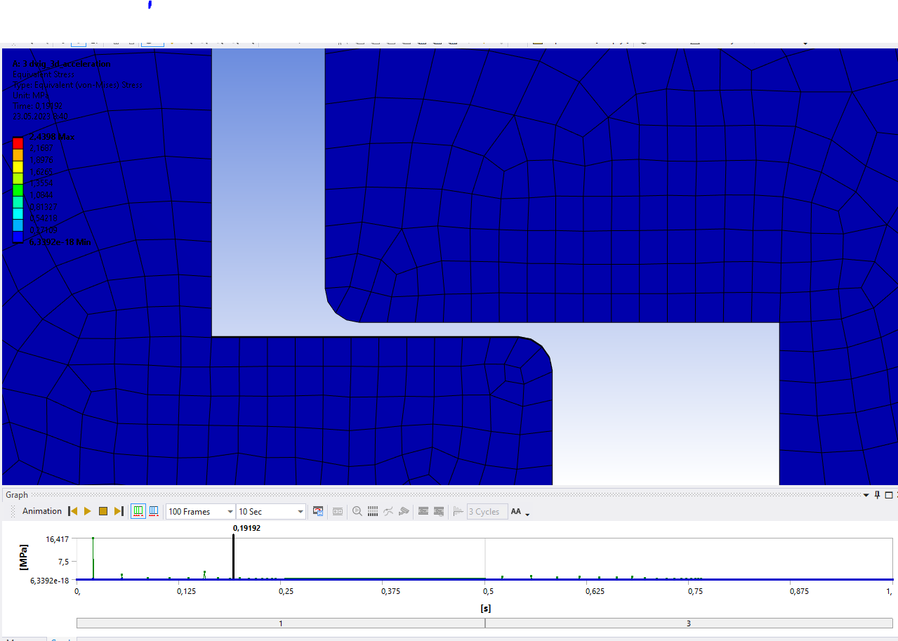
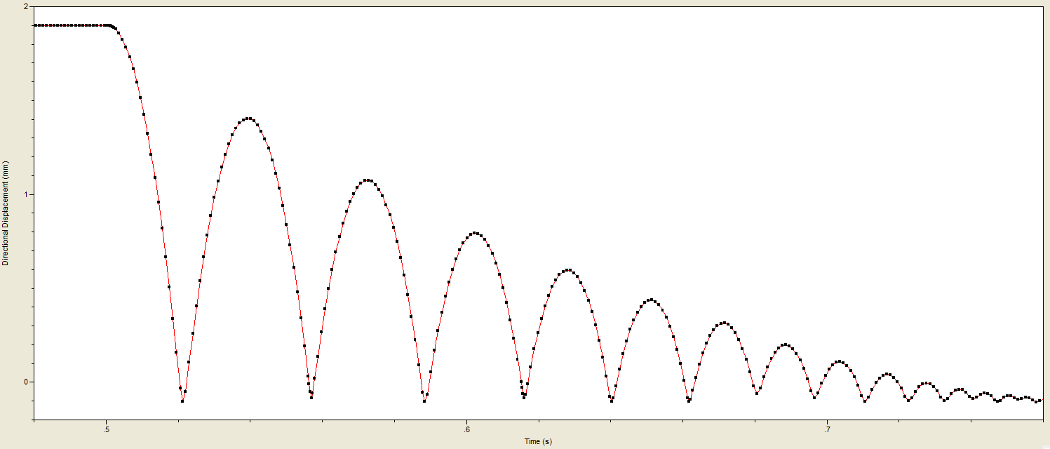
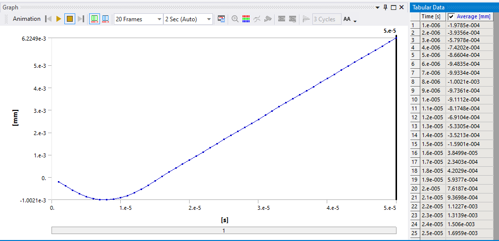
      Put a Directional Deformation and a Directional Velocity plot in the X direction on a corner vertex of the moving part, distant from the contact surface. Here we see the damping working on the part.

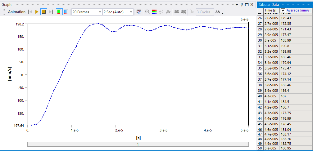
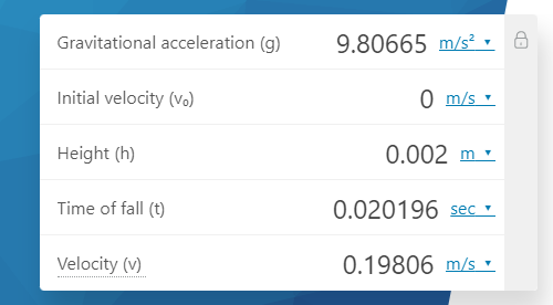
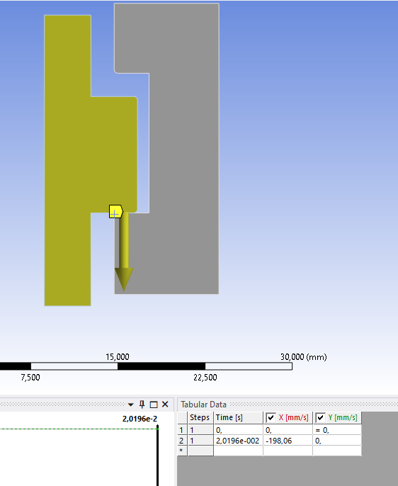
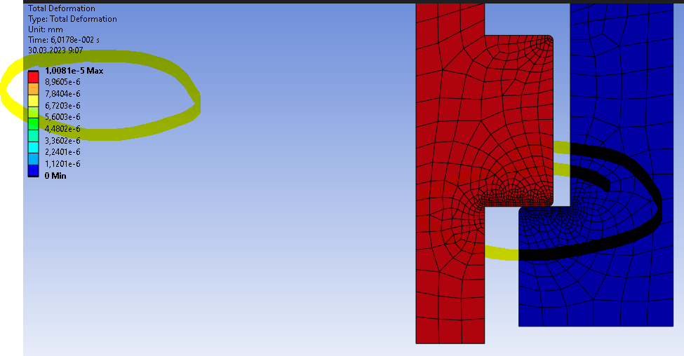
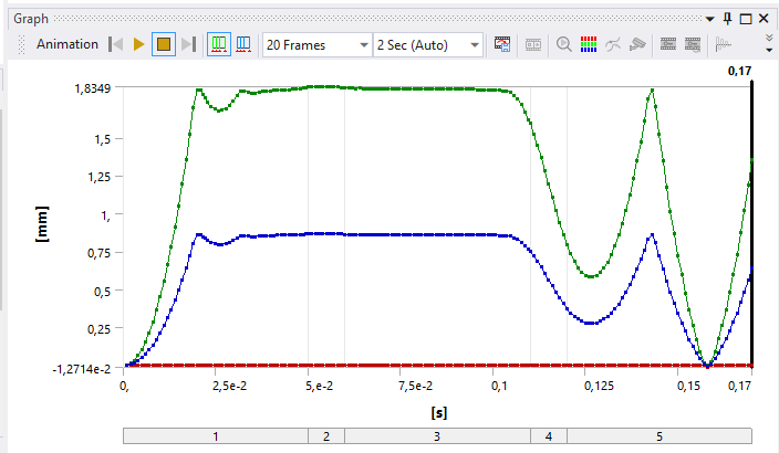
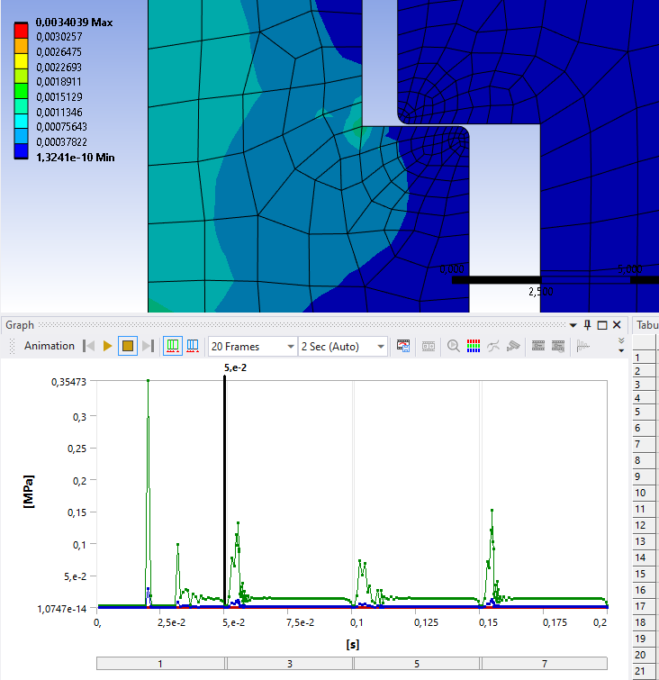
      You can see that at t=1.6e-5 s the bounce is finished and the contact starts to separate, moving away at about 181 mm/s. The other end of the slot is 2 mm away. This is where the free fall began and gave the 198 mm/s initial velocity at impact. Since the departing velocity from the impact is only 181 mm/s due to damping and frictional contact losses, the part would not reach a 2 mm displacement if Gravity in the -X direction was included in the simulation. Gravity was not in the model, but including it makes an insignificant change during the 1.6e-5 s of the impact event.

      If there was no friction in the support of the moving part, it would make a second impact at 181 mm/s instead of 198 mm/s for the first impact. In reality, there is likely to be friction both going up and falling down. This is a 2D simulation so there is no motion out of plane. In a 3D simulation the bounce would not travel perfectly along the X axis, but would rotate and go off at some small angle so the second impact would not be perfectly level with the surface, dissapiting more energy than the first impact.

      • javat33489
        Subscriber

        Thanks for the great and complete answer.

        1. Please tell me how you got 33683 Hz in modal analysis? I don't get that many:
        2. How can the process be looped so that the moving part moves at a speed towards the stationary part, for example, 50 times, thereby deforming the stationary part each time?
    • peteroznewman
      Subscriber
      1. I did two Modal analyses, one had the result you show, which is more relevant, and one was of the moving piece alone, which was 33 kHz.
      2. Let the simulation run for a few weeks. The impacts will continue until there are no more bounces and the part has come to rest.
      • javat33489
        Subscriber
        1. I did two Modal analyses, one had the result you show, which is more relevant, and one was of the moving piece alone, which was 33 kHz.

        Tell me how did you do it? It doesn't work for me either.

        1. Let the simulation run for a few weeks. The impacts will continue until there are no more bounces and the part has come to rest.

        You did not understand me. In life, two pipes are connected by grooves and dowels. And they can hit many times. Can I set fall speed and return displacement 25 times?

    • peteroznewman
      Subscriber
      1. I noticed that when I first ran Modal, the Frictionless Support did not behave properly. Is that what you saw when you ran Modal? I deleted the Frictionless Support and put in a Displacement BC with just one DOF set to 0 and the others Free.
      2. Apply an acceleration time history of say 50 seconds that causes the part to hit each end 25 times and let the simulation run for many weeks.
    • javat33489
      Subscriber
      1. I noticed that when I first ran Modal, the Frictionless Support did not behave properly. Is that what you saw when you ran Modal? I deleted the Frictionless Support and put in a Displacement BC with just one DOF set to 0 and the others Free.

      Thank you sir! I will try!

      1. Apply an acceleration time history of say 50 seconds that causes the part to hit each end 25 times and let the simulation run for many weeks.

      Thank you, the task in this setting is clear. I have an idea, I will try to ask the task using force and displacement 50 times

    • peteroznewman
      Subscriber

      Here is an acceleration-time history that will cause the mass to fall to each end of the slot along the X axis.

      t (s)        ax(m/s^2)
      0.0            -9.81
      1.0            -9.81
      1.00001     9.81
      2.0             9.81
      2.00001    -9.81
      3.0            -9.81
      3.00001     9.81
      4.0             9.81
      ...               ...

      this shows the first four impacts.

      • javat33489
        Subscriber

        Thank you very much for the answer! Maybe you have a typo in the table?

        Shouldn't she look like this? Do you have many cons?

        OK. I did two calculations, with your table and with the table that I suggested.

        1. My table. Results:

        ANIMATION

        2. Your table. Results:

        ANIMATION

        The solver settings still contain the data of the first modal analysis mode. Is it necessary in such a calculation with acceleration?

    • peteroznewman
      Subscriber

      The acceleration time history should be a square wave, not a sawtooth.  Acceleration due to gravity is a constant over time.  The trick is to change the sign of gravity so it can be inverted in a fraction of a millisecond.

      There seems to be something very wrong with your transient simulation. Starting from rest, the part should fall 2 mm in 0.02 seconds.  Since the part is already at the bottom, remove the initial velocity so it starts from rest at t=0.  Now change the sign on all the accelerations.  You should see the part fall upward and hit the top stop in 0.02 seconds and bounce on the top for a while, then at t=1.00001 the acceleration changes sign and the part will fall down. It should hit the bottom stop at 1.02 seconds and bounce.  I think the damping is adding a huge viscous force so it's like the gap is filled with oil and the part hardly moves at all in 1 second.  Remove all damping and solve again.

      • javat33489
        Subscriber

        ok i did it in your way.

        I did the calculation without damping, and this is what happened:


        what do you think about this?

    • peteroznewman
      Subscriber

      There seems to be something very wrong with your transient simulation. Starting from rest, the part should fall 2 mm in 0.02 seconds under an acceleration of 9.81 m/s^2.

      • javat33489
        Subscriber

        I think I need to change the minus signs in places?

    • peteroznewman
      Subscriber

      No. The fixed part is blue, the moving part is red. A negative acceleration along the X axis causes the unrestrained red part to move in the +X direction. 

      • javat33489
        Subscriber

        But then I did everything right.

        But why not right?

        ARCHIVE

    • peteroznewman
      Subscriber

      Rebuild your model from the geometry. A new model works properly.

      Object falls about 2 mm in 0.020 seconds.

      Did you ever change the setting on the Geometry from 3D to 2D after you started? You must not do that.

      • javat33489
        Subscriber

        What has changed in geometry? The decision time has changed. Can you attach a file please?

    • peteroznewman
      Subscriber

      Nothing in geometry changed. I just copied the geometry over, fed that into a new Transient Structural, added a fixed support, a displacement of Y = 0 for the moving part and Standard Earth gravity. One step with an end time of 0.02 s and an Initial and Maximum Time Increment of 0.001 s.

      https://jmp.sh/P8TzwqrF

      • javat33489
        Subscriber
        Sorry. But we again returned to my first solution, where I dropped the part only once. Then I said that the part falls several times and you suggested using acceleration and showed me a table of 4 falls. In the last option you suggested, can I use gravity + displacement? Raise and release a moving part several times?
    • peteroznewman
      Subscriber

      I showed you how to use a square waveform for the acceleration-time history to cause the part to fall to each end multiple times. The displacement boundary condition is equivalent to the Frictionless Support to allow the part to slide along the axis.  All I am saying is to rebuild the model from scratch because your model is broken and can't do a simple single drop!


      • javat33489
        Subscriber

        I'm confused?

        I will try to collect again.

    • peteroznewman
      Subscriber

      The method to build up a model is to take it a step at a time.  The first thing to get working is a single drop. The part should hit, bounce up and fall down and hit again and the bounce should get smaller and smaller until there are no more bounces. Can you get that first model working? 

      I tried and there are problems even in this simplest model. Do you see after impact, the first bounce looks great, but then the part starts shuttling back and forth between the ends and seems to be gaining energy, not losing energy.  This model has zero damping. This has the acceleration constant during the entire time.

      • javat33489
        Subscriber

        Thank you sir.

        I did everything from the beginning. And I tried to start with one fall, but I applied acceleration, so that later I could scale it up by several falls.

        It turned out like this, it works:

        ANIMATION:


        _________________________________________

        Why is there a gap? Is it because of the pinball?


        By the way, pinball affects stress, why?

        _________________________________

        Then I wanted to make a few accents, but I did not succeed. First I tried to return the part after being dropped by the displacement - it doesn't work. Then I tried to pull back the part using acceleration as you recommended earlier - that doesn't work either.

        _________________________________________

        Can you tell me how to make a multiple drop?


    • peteroznewman
      Subscriber

      You need to program a “square wave” into the acceleration. The sign of the acceleration has to change over 0.001 s or smaller.

                0.000  -9806.
      Step 1    0.050  -9806.
      Step 3    0.051  +9806.
      Step 4    0.100  +9806.
      Step 5    0.101  -9806.
      Step 6    0.150  -9806.
      Step 7    0.151  +9806.
      Step 8    0.200  +9806.
      • javat33489
        Subscriber

        Oh. Thank you very much, I will try and let you know later.

        You are a very smart professional, could you answer here too? LINK

      • javat33489
        Subscriber

        Sorry sir. This does not work.


        ARCHIVE

    • peteroznewman
      Subscriber

      It seems this 2D analysis has a defect that prevents the mass from falling after it bounces and settles on the far end when the gravity vector changes direction.  It may be worth building a small 3D model to see if a 3D model has the same problem.  Are you interested to try that out?

      • javat33489
        Subscriber

        I thought so too and have already prepared the model. I will make this option and write to you.

      • javat33489
        Subscriber

        You are a very smart professional, could you answer here too? LINK

      • javat33489
        Subscriber

        Sorry sir. This does not work in 3d:


        ARCHIVE

    • javat33489
      Subscriber

      What do you think about this?

    • javat33489
      Subscriber

      I need help guys

    • javat33489
      Subscriber
      I need help guys
    • peteroznewman
      Subscriber

      We need someone from Ansys to take a look at the fundamental problem: when the acceleration vector reverses in a 3-step solution, the mass does not fall back to the end it started from.

      This thread is now very long which makes it less interesting for someone else besides me to answer.

      I suggest you start a New Discussion. Keep in mind that Ansys employees are not allowed to download any model or click on any links. You have to insert all the images in the description to fully explain the simplest possible model, what you expected and what you got.  I will not answer this new thread. Let it sit for a few days and wait for someone from Ansys to pick it up.

    • peteroznewman
      Subscriber

      I saw your other post but you didn't provide enough detail for someone to recreate the problem. Show the contact details. Show the joints and boundary conditons. Show the Analysis Settings.  

      I suggested you limit the example to 3 steps but you show 7 steps.

      It would be helpful to show a directional deformation graph to compliment the velocity data.

      • javat33489
        Subscriber

        Hello sir. Perhaps my mistake is related to the damping factor. I changed the il in two contacts like this:

        and this is what came out:


        What do you say to that sir?

    • peteroznewman
      Subscriber

      It would be far more helpful to show a directional deformation graph which is much easier for me to understand than the velocity data.

      It would be helpful to show the 3-step solution with one reversal of acceleration. Make sure the time steps have a long enough duration to allow the part to come to zero velocity before the acceleration reverses.


      • javat33489
        Subscriber

        Ok I did three moves and played around with the damping factor in the pins, here are the three versions:

        1. 


        2.


        3. 

        4. Without dumping factor:

        I use a very small step: 0.00001/0.0000001/0.0001


    • javat33489
      Subscriber
    • peteroznewman
      Subscriber

      Great!  I hope you see how much easier it is to interpret the results by plotting deformation instead of velocity.

      Configurations 1, 2, and 4 give garbage results.

      Configuration 3 has some potential to give good results but the initial motion seems corrupted. Make sure the contact is Near Open before the simulation starts. There should be a clean parabolic curve of constant acceleration for a part falling from rest like I show below. You can see a parabola for Step 3 of your simulation.

      Double the end time of Step 1 so that the part comes to rest before the rapid acceleration reversal step, then make sure the end time for Step 3 is also doubled so that you have time to see the bouncing and the part come to rest.

      • javat33489
        Subscriber

        OK I'll try. By the way, I forgot to say that the result number 4 is with the included predict for impact.

      • javat33489
        Subscriber

        Excuse me sir. But all that you described is impossible to do.

        1. An even parabola is not done at the beginning of the movement, no matter what I do.
        2. If I increase the time of steps 1 and 3, the part starts to fly through another part and nothing helps.

        ARCHIVE

    • peteroznewman
      Subscriber

      I looked at your archive and found out why you don’t have a displacement parabola for a part falling from rest. The reason is you have an Initial Condition for Velocity.  Delete that and you will get what I was describing. In the example below, I suppressed both contacts.


      To prevent the parts from passing through each other, try turning on Predict for Impact.

    • peteroznewman
      Subscriber

      The 4 graphs below have zero Damping under the Analysis Settings. The Stabilization Damping Factor is under the Contact Details for Frictional Contact.

      Stabilization Damping Factor = 0.0  This looks normal.

      Stabilization Damping Factor = 0.05  this looks over-damped.

      Stabilization Damping Factor = 0.1 this looks somewhat normal.

      Stabilization Damping Factor = 0.2  non-physical behavior: larger second bounce.

      The graphs below have various levels of Damping under the Analysis Settings. The Stabilization Damping Factor is under the Contact Details for Frictional Contact was set to 0.

      This first result doesn’t look physical.

      Reduced damping by a factor of 10. This looks better than the larger damping value in the first trial.

      • javat33489
        Subscriber

        Thank you very much for your analysis. I also set the damping factor to 0.

        I had a mistake, I forgot to remove the initial acceleration, thanks. But it did not help.

        I removed the initial acceleration, set the predict for impact, and set the damping factor to 0, this is what happened:

        When I add time to the first step, the part stops moving at all:

        It seems I've tried everything.

        • peteroznewman
          Subscriber

          When you added time to the first step, that may have messed up the acceleration load. Check it carefully.

    • peteroznewman
      Subscriber

      Here is my 3 step solution. Note the clean falling down after the acceleration reversal in step 2. Unfortunately, there is non-physical bounces occuring in step 3.  This model has 0 contact stabilization but has Damping defined in the Analysis Settings as shown below.

      Here is the solution with contact settings shown below and 0 damping under Analysis Settings. 

      This is the best configuration for multiple impacts!

    • peteroznewman
      Subscriber

      Archive for the best configuration.

      • javat33489
        Subscriber

        Thank you very much sir! Today I also did a lot of tests, but nothing happened, maybe your archive will give answers to my questions! I'll take a look and report back! Thanks for spending time on my project.


        I have one question about the picture, where did 1000 hertz come from?

    • peteroznewman
      Subscriber

      I typed it in so Ansys could use that to convert the 0.05 Damping Ratio into a Stiffness Coefficient.

      • javat33489
        Subscriber

        Hello sir. I have a question. Why doesn't the part drop right away? Does it bounce off the air and then just touch another part?

    • peteroznewman
      Subscriber

      The part does drop right away. Change your animation settings from Uniformly Distributed to show every frame saved.

      • javat33489
        Subscriber

        I set the maximum animation parameters to 100 frames and 10 seconds.

        I apologize in advance for the large number of frames. I took 25 shots showing how the part moves. On frames 6 and 10 you can see how the part is repelled from the air:

    • javat33489
      Subscriber
      What do you think?
    • peteroznewman
      Subscriber

      There is no "air" in the simulation.

      In my archive from my reply above, the bouncing behaves very well.

      • javat33489
        Subscriber

        It's probably just an animation that shows it that way. I understand. Thank you very much for your help! I'll try on the real details.

Viewing 40 reply threads
  • The topic ‘Falling under the force of gravity into a transient’ is closed to new replies.