-
-
February 27, 2023 at 5:16 pm
Fernando Hernández
SubscriberHi there!
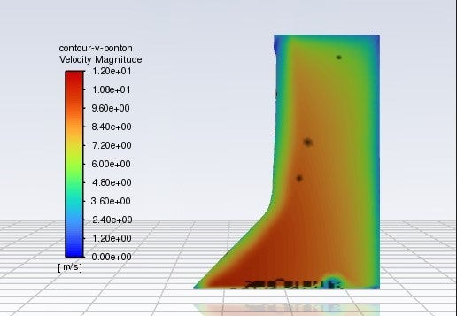
I am currently performing a 3D analysis of a Formula Student car. The objective is to measure the air mass flow rate that passes through the sidepods, so I have created a surface at the sidepod entry and I have defined a Surface -> Mass Flow Rate report on that surface.The X velocity contour can be seen in the attached picture (I have assumed that the dark spots are just a visual glitch, but maybe I'm wrong). The area of the surface is around 0.1 m2. So according to my calculations the mass flow rate through it should be around 1 kg/s.
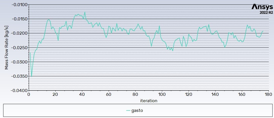
However, as seen in the next picture, the resulting mass flow rate varies between 0.015 and 0.025 kg/s.
Am I doing something wrong? Is this mass flow rate measuring method incorrect?
I would appreciate any help. Thank you in advance.
Kind regards!
-
February 28, 2023 at 11:20 am
Rob
Forum ModeratorYou may need to run a few more iterations. Most real models don't converge in 180 iterations. How do the residuals look?
Please replot the contour with node values off, that's a good way to check the mesh resolution.
-
- The topic ‘Measuring mass flow rate through a surface’ is closed to new replies.


-
4602
-
1510
-
1386
-
1209
-
1021

© 2025 Copyright ANSYS, Inc. All rights reserved.


