-
-
February 24, 2023 at 7:16 pm
thach-hoang.nguyen
SubscriberHello eveyone,
I have a model like in the second photo with rectangle cross section but when i meshed the model, i received the meshed model like in the picture below. Is this normal? and can i ask where is this problem comes from? And if anyone knows how to resolve this problem.
-
February 24, 2023 at 9:49 pm
peteroznewman
SubscriberOn the Display tab, click the Thick Shells and Beams button and the Show Mesh button.
You can also click the Cross Section button to show that on the Geometry without showing the mesh.
-
February 25, 2023 at 8:37 am
-
-
February 25, 2023 at 8:42 pm
peteroznewman
Subscriber
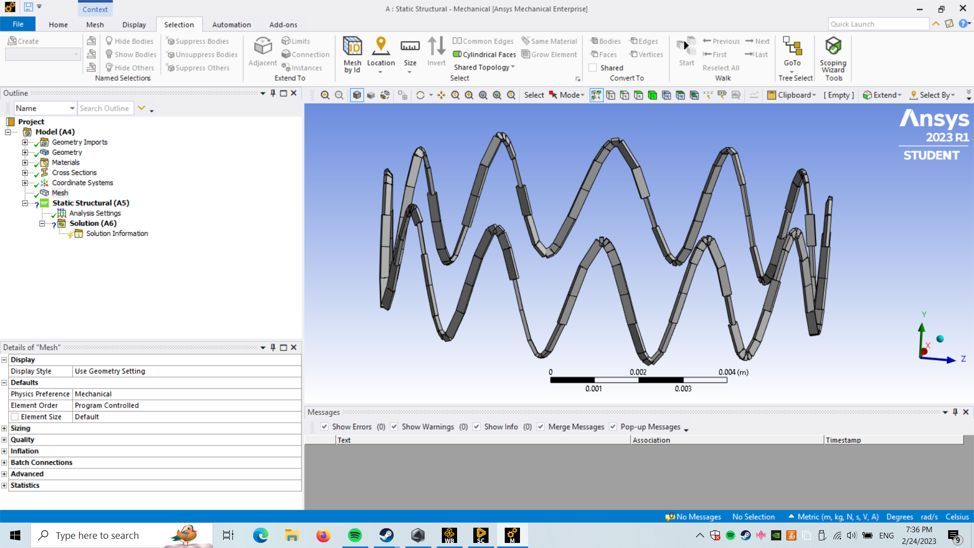
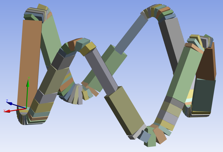
Yes, this is a problem. I made my own set of curves in SpaceClaim, assigned a rectangular beam cross-section and got this mess.
Looking at the documentation, it seems the ability to control beam orientation is superior in DesignModeler.
However, importing the SpaceClaim file into DesignModeler did not make it simple to edit the orientation.
I will have to start over in DesignModeler and import the curves, then create Line Bodies and see if I can succeed.
-
February 25, 2023 at 11:19 pm
thach-hoang.nguyen
SubscriberI have tried both DesignModeler and SpaceClaim but they give the same result. If you succed can you show me the way. Thank you so much
-
-
- The topic ‘Cross section and mesh problem’ is closed to new replies.
- The legend values are not changing.
- LPBF Simulation of dissimilar materials in ANSYS mechanical (Thermal Transient)
- Convergence error in modal analysis
- APDL, memory, solid
- How to model a bimodular material in Mechanical
- Meaning of the error
- Simulate a fan on the end of shaft
- Nonlinear load cases combinations
- Real Life Example of a non-symmetric eigenvalue problem
- How can the results of Pressures and Motions for all elements be obtained?
-
3882
-
1414
-
1241
-
1118
-
1015
© 2025 Copyright ANSYS, Inc. All rights reserved.