-
-
February 21, 2023 at 10:52 pm
azbader
SubscriberHello,
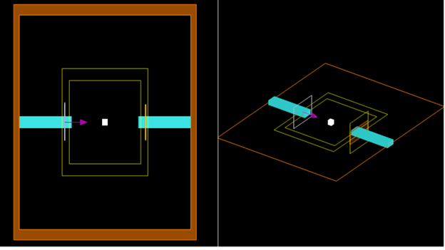
We are interested in the inverse design of a waveguide with topology optimization (please see the schematics below) and we have a number of questions regarding this optimization problem.
We have used the “Inverse Design of a Splitter Using Topology Optimization” example and modified the code to get to our desired design.
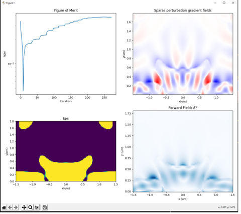
When we run the Python code that performs the optimization, we are interested in checking for various FOMs. However, we see that the results fail to follow the targeted FOM. Please see below for the case when Target_FOM =0.5.
The documentation of “Inverse Design of a Splitter Using Topology Optimization” example says that FOM=0.5- T_Up (please see : https://optics.ansys.com/hc/en-us/articles/1500007182141-Inverse-Design-of-a-Splitter-Using-Topology-Optimization)
Is the T_Up the same as the Target_FOM in the code? And is there a chance to change the FOM formulation altogether, or do we have to use that? Any chance of having access to the FOM function file?
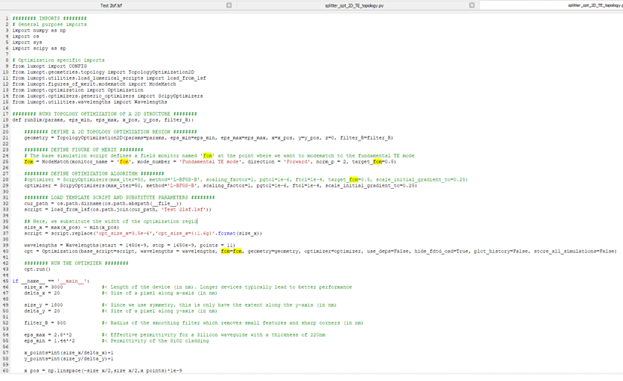
This is the code we used:
· Also, is it possible to get a frequency-dependent FOM in a problem like this?
Thanks a lot for your help in advance!
-
February 23, 2023 at 7:33 pm
Guilin Sun
Ansys EmployeeYes, you are right: “Inverse design using Topology Optimization enables automatic generation of devices that are optimized for a user-specified figure of merit (FOM). In this Y-splitter example, we want to maximize T_up, the fraction of the total input energy that is transmitted into the upper arm. Since we will enforce symmetry in the y-direction, the maximal value of the FOM will be 0.5. For visualization, instead of directly plotting T_up, we show the insertion loss, so FOM=0.5 – T_up.”
Currently the optimization is to target a scalar result, which means it has only one value.
-
February 23, 2023 at 9:48 pm
azbader
SubscriberThank you, Guilin for your help!
Following up with the definition of the FOM, you mentioned that the FOM that is plotted is the inserion loss. What about what is defined in the python code as Target_FOM, is that also the insertion loss or is that T_Up?
Thanks a lot!
Azadeh
-
February 23, 2023 at 10:25 pm
Guilin Sun
Ansys EmployeeIt is FOM=0.5 – T_up, which they call it insertion loss. You could change it to T_up if you want.
-
February 23, 2023 at 10:41 pm
azbader
SubscriberIn the documentation of the example of Y splitter, when FOM_Target is set to 0.5 in the code, the illustrated figure for FOM is converging to zero (please see the attached screenshot). This shows a mismatch between what we define as Target_FOM in the code and what is being plotted as the final FOM. So, I wonder what really Target_FOM in the code is? Keeping in mind that, in the code, T_up is not defined anywhere. We only have Target_FOM.
-
February 23, 2023 at 11:35 pm
Taylor Robertson
Ansys EmployeeHello Azbader,
I would suggest the following article. https://optics.ansys.com/hc/en-us/articles/360050995394
The target_fom is simply an option used for plotting, I believe that what you want is the target_T_fwd to specify the output power.
target_T_fwd: float or function
A function which will take the number of Wavelengths points and return values [0,1]. Usually passed as a lambda function or a single float value for single wavelength FOM. To specify a more advanced spectrum one can define a function, it may be helpful to use, numpy windows as a template.
target_fom: float
A target value for the figure of merit. This will change the behavior of the printing and plotting only. If this is enabled, by setting a value other than 0.0, the distance of the current FOM is given. Default = 0.0
Best,
-
- The topic ‘Topology Inverse Design’ is closed to new replies.


-
4613
-
1530
-
1386
-
1209
-
1021

© 2025 Copyright ANSYS, Inc. All rights reserved.


