TAGGED: #fluent-#cfd-#ansys, density, dynamic-mesh, error
-
-
February 17, 2023 at 7:10 am
Yagiz Guzelcan
SubscriberHello everyone.
I am working with 2D simulation with dynamic mesh. My geometry looks like that: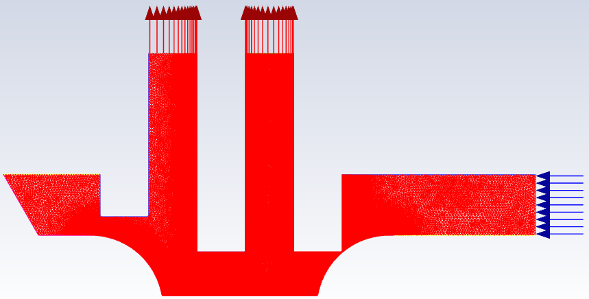
I have 1 inlet (210 bar) and 2 outlets (0 bar). There is a motion and is defined via UDF. When the simulation starts, motion starts as well. Normally, I must use hydraulic oil properties which has 860 kg/m3 density. When I use hydrualic oil density value, the results coming out are wrong. When I switch to air, which has 1.225 kg/m3 density, the results coming are seem to be true.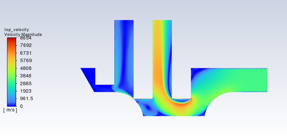
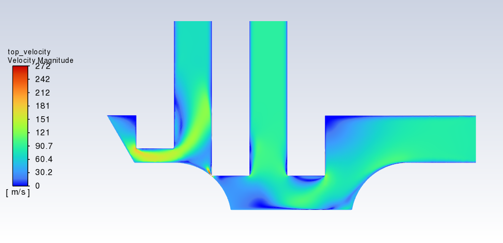
The upper one is the result of air. Velocity values are wrong; however, the motion of the fluid from inlet to outlet ports are correct.
The lower one is the result of oil. Velocity values may be wrong or true; however, the motion from inlet to outlet ports are definetly wrong. Here is the 1 time step after the beginning when I use oil: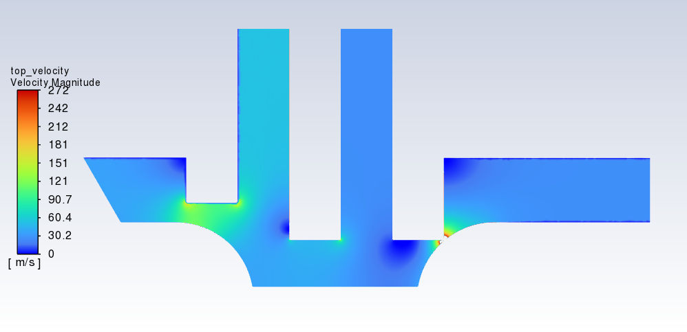 It begins like that and afterwards the results are coming wrong.
 For the both cases, the residuals are not diverging. However, for oil, the residuals are unstable compared to air residuals. Here is the graphs of residuals:
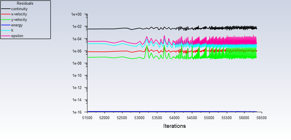
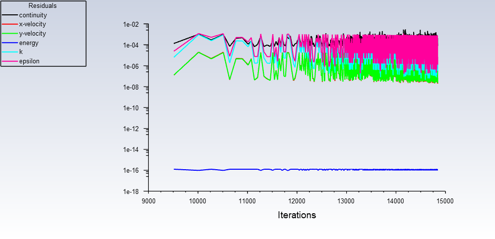
Upper one is for air; lower one is for oil.As a result, using high density value creates something with the simulation and makes the results wrong. I am using pressure-based solver with second order interpolators. Additionally, I have tried different approaches. I changed method, solver, spatial discretization types for all properties but still have the same issue.
What do you think about this problem? And, how can I solve it and make the result true for hydraulic oil density value?
(I have also animations of pressure and velocity for both simulations with air and oil. If you want to see it I can send a link of the animations as well.)
Thanks. -
February 17, 2023 at 9:55 am
SRP
Ansys EmployeeHi,
How did you initialize in both the cases?
I suggest you to start solution with lower time step.Lowering the time step will enhance convergence.If you experience difficulty in getting convergence for desired time step, use lower time step for initial transients, once you get good convergence gradually increase time step to required value.
Thank you
-
February 17, 2023 at 10:47 am
Yagiz Guzelcan
Subscriber@SRP
Hello, thank you for your attention.
In both cases the simulations is initialized via hybrid initialization.
I am currently using 4.97e-9 time step for both cases. My time step is very low but I will try using much lower time step as you said. However, I have no problems on convergence. Both cases are congerved to a value. The problem is that for the case where I use oil as a working fluid, congerved results are not physically meaningful.
Thanks.
-
-
February 17, 2023 at 1:29 pm
Rob
Forum ModeratorIf it's transient, what should be the starting condition in the domain? Ie should the pressure be a single value, split by the narrow point?
-
February 17, 2023 at 1:51 pm
Yagiz Guzelcan
SubscriberThanks for your answer,
I don't think I fully understand your answer. The simulation is transient, and I am utilizing dynamic mesh motion as well. The true geometry I refer to has this type of geometry. Pressure inlet of 210 bar is unchangable as well as pressure outlet ports of 0 bar. Narrow point you mention is actually a wall in the real geometry. To do the analysis without having any problems at the beginning, I simply remove the touch of the two walls which are coinciding in one point and replace the whole region with small meshed region so the fluid can flow.
Thanks.
-
-
February 17, 2023 at 1:53 pm
Rob
Forum ModeratorOK, what is the domain pressure at t=0 ? In reality and in your CFD model.
-
February 17, 2023 at 1:59 pm
Yagiz Guzelcan
SubscriberThanks for you answer,
In reality there will be no flow for t<0. When t=0, the flow begins from 210 bar source and exiting the geometry from two outlet ports with 0 bar.
In my model, the first narrow point restricts flow for t<0. When t=0, the motion begins and the narrow part gets bigger and the flow proceeds towards to the both exit ports. When the motion is done, the second narrow part is created on the left side and restricts flow to go out from the left outlet port.
Thanks.
-
-
February 17, 2023 at 2:13 pm
Rob
Forum ModeratorThere may not be any flow but there will be a pressure field. That will then determine how the flow behaves, and the density if it's compressible.
-
February 20, 2023 at 8:37 am
Yagiz Guzelcan
SubscriberThanks for your answer,
The area open to outlet ports have 0 bar while the area open to inlet port has 210 bar of pressure. The fluid is taken as incompressible. In Fluent, constant density selected for both cases.
Thanks.
-
-
February 20, 2023 at 9:26 am
Rob
Forum ModeratorIncompressible at 210bar?
With pressure boundaries the mass flow is a result, rather than being defined. With a good initial condition that's OK, if you've not been careful, or the there are multiple numerically valid results the solution may be a little odd. That's why we don't just take residual values when checking for convergence.
-
February 20, 2023 at 10:05 am
Yagiz Guzelcan
SubscriberThanks for your answer,
My model has hydraulic oil as a working fluid. That is why I take it as incompressible fluid. For both cases (air and oil) the solution converges. However, for the case of oil, converged result is not I expected to happen in the system. There maybe another numerical solution which the program is converged to as you explanied. The boundary conditions must be pressure type. I cannot change that. However maybe I can change something else to get expected results.
What should I change to get expected results? After I posted my question, I have tried that I started the simulation for air and after the results were converging I switched to hydraulic oil (in terms of density). Nevertheless, at the moment I changed the density, results were completely off and at the end the simulation I got the same result as I used oil density at the beginning of the simulation.
Thanks.
-
-
February 20, 2023 at 1:46 pm
Rob
Forum ModeratorPlease post the pressure field at t=0
-
February 21, 2023 at 7:14 am
-
-
February 21, 2023 at 9:40 am
Rob
Forum ModeratorWhat's the operating pressure? The only issue with the above is going to be keeping the solver stable as the gap opens. I assume the gap isn't closed to start with as that will mess with the solver schemes.
-
February 21, 2023 at 9:44 am
Yagiz Guzelcan
SubscriberYou are correct. The gap is not fully closed. There is a little gap between two sides. Operating pressure is 101325 Pa.
Thanks
-
-
February 21, 2023 at 9:55 am
Rob
Forum ModeratorSounds sensible. I suspect it's a solver where the flow jet entrains too much material from one of the two outlets and then pushes it all out of the other. What are you expecting to see?
-
February 21, 2023 at 1:27 pm
Yagiz Guzelcan
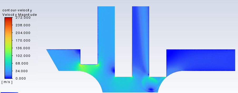
SubscriberAt the beginning I posted the velocity contour in which air was the working fluid. I expect to have that type of result. I do not expect to have any fluid flow going out or coming in at the end of the result.
Summary-> What I expect is like that: (this result is for air as I mentioned in my first post)
What I get: (this result is for oil as I mentioned in my first post)
Both results are taken at the end of the simulation.
I asked my supervisor about it and he said no problem. However, I belive there is something off with this result.
Thanks.
-
-
February 21, 2023 at 4:34 pm
Rob
Forum ModeratorHow does the flow look early on in the model?
-
February 22, 2023 at 10:23 am
-
-
February 22, 2023 at 10:27 am
Rob
Forum ModeratorI can see how the flow is evolving at the restriction, that makes sense. The remainder of the flow field doesn't. How did you initialise the flow?
-
February 22, 2023 at 10:31 am
Yagiz Guzelcan
SubscriberThe initialization done via using Hybrid initialization with 30 iterations.
Thanks.
-
-
February 22, 2023 at 11:21 am
Rob
Forum ModeratorAnd what is the velocity at t=0? I suggest reading up on what hybrid initialisation is doing, and then tell me why it's often a bad idea in transient flow models.
-
March 23, 2023 at 11:07 am
Yagiz Guzelcan
SubscriberHello,
I couldnt find any useful source on hybrid initialization. Could you tell me why?
Thanks.
-
-
March 23, 2023 at 11:45 am
Rob
Forum Moderatorhttps://ansyshelp.ansys.com/account/Secured?returnurl=/Views/Secured/corp/v231/en/flu_ug/flu_ug_sec_init_hybrid.html The starting point is based on the boundary conditions, so will take inlet and outlet conditions into account over the whole domain.
-
- The topic ‘Density of fluid affects the results and it makes the result wrong.’ is closed to new replies.


-
4723
-
1565
-
1386
-
1242
-
1021

© 2026 Copyright ANSYS, Inc. All rights reserved.


