TAGGED: contact, mechanical, rigid-body
-
-
February 1, 2023 at 4:05 pm
henrique.geraissate
SubscriberHello,
I am trying to set up a simulation to investigate deformation and stress on a tiny cylindrical part when pressed against a rigid reference, just like the picture below:
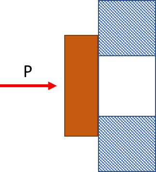
The rigid part (blue) has a hole in it, and the flexible one (orange) is a solid cylinder, so that the contact between both is a ring-area. I am performing a 3D analysis.
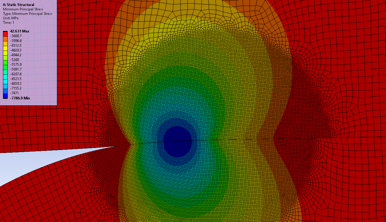
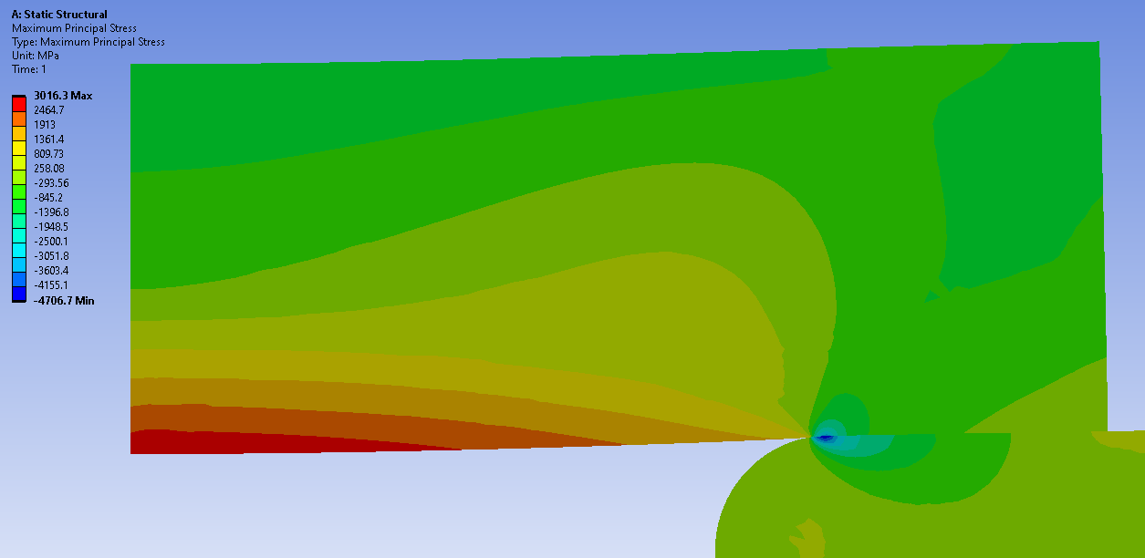
Initially, I had not modeled the blue part, and considered only the orange one with a defined ring-area on its back, to which I applied fixed support. That doesn't seem to work great, as the stresses in the support region are artificially high and would get higher as I refined the mesh.
Second approach was modeling the blue part, set it up as a rigid body and fix it with a body-ground joint. Then, I applied bonded contact between the parts (they will indeed be glued together eventually). The problem with the artificially high stresses seems to persist.
Lastly, I've set the contact as frictional. The max stress value has lowered, but I am still not sure what is the best way to proceed with this kind of simulation.
Could anyone please share some insights on how you would set it up?
Thanks in advance,
Henrique -
February 2, 2023 at 9:45 am
Erik Kostson
Ansys EmployeeÂ
Hi
Â
The last approach is the most realistic I suppose (frictional contact) as it perhaps represents the real situation. Perhaps have all parts flexible as this is more realistic.
Â
You can still get some high artificial stresses perhaps (say near contact areas).
Â
See more about this (artificial stresses) here:
https://www.youtube.com/watch?v=iTqPgcTurXc
Â
Â
Â
All the best
Erik
Â
-
February 2, 2023 at 1:18 pm
peteroznewman
SubscriberHi Henrique,
If the parts will eventually be glued together, is the stress without glue relevant?
Some adhesive materials are more flexible than the materials that they bond together. What type of glue are you using? What will be the thickness of the glue between the parts? To get accurate stresses, you will want to include the thin layer of glue between the parts in the simulation, and use 3 or 4 linear elements through the thickness of the glue.
-
February 3, 2023 at 8:53 am
henrique.geraissate
SubscriberHi Erik and Peter, thanks for the reply!
I had already seen the video that Erik sent. It was really helpful indeed, but I am afraid it did not solve all of my problems hehe. But I am happy to hear that I may be walking the right path.
Peter, this is part of much more complex assembly, which is a High Pressure Cell to be used in spectroscopy experiments. What I am trying to simulate is a diamond window to be used within this cell, but initially I want to know only if the window itself would withstand the high pressure of 1GPa. I have some analytical models and I would like to compare the analytical results with the simulation. This leads to my next question:
Although the diamond window dimensions (Diameter = 5mm and Thickness = 1 mm) are not exactly compatible with thin plates modeling, I am using those equations thinking that I may acquire a more conservative results from it. In Ansys, I am now exploring the approach of modelling again only the diamond (orange) as a surface, and perform the calculations with shell elements and boundary conditions applied to the edges. Is there any recommendation on the use of shell elements in terms of dimensions? Is it ok to continue like that?
And trying to answer the second part of your comments, I am not yet sure if the parts are going to be glued together or not. Another possibility would be "guiding" the external diameter through a well machined hole. I understand this choices as, for example, having the window simply supported (without glue) or with fixed ends (glued), which changes the boundary conditions (for both the analytical and Ansys model). So my idea is compare this two situations to see if the maximum stress would reach the yield strength of diamond.
Any comments on these?
I hope I could clarify a bit more :)
-
February 3, 2023 at 8:47 pm
peteroznewman
SubscriberHi Henrique,
I suggest you model the window and a shoulder as an Axisymmetric model. In the XY plane, the Y axis is the axis of revolution. Draw a rectangular surface from the origin 2.5 mm along the X axis and 1 mm along the Y axis. This defines your circular 5 mm diameter window in an axisymmetric model. Then draw a rectangular surface starting at X = 1.5, on the Y axis and go out to X = 3.5 and down to Y = -2.0 to make the blue part with a 2x2 mm cross section of an annular ring for the window to sit on. If you add a small radius on the corner, you can avoid high stress due to that sharp corner.
What version of ANSYS do you use? I can make that model very quickly for you to try out.
After you know the window can take the pressure, you will want to consider how to seal the window against the metal vessel.
What are the properties you have for diamond?
-
February 6, 2023 at 8:30 am
henrique.geraissate
SubscriberHi Peter,
I am using ANSYS 2021 R2. I really appreciate your availability and I accept that help, as I am not exactly familiar in setting up 2D Axisymmetric models.
For the diamond, I'm using:
E = 1000 GPa
v = 0.07
d = 3520 kg/m3From my last approach modelling the window as a surface, I could get stress results that well agrees with the analytical solution for thin plates model, and from them it seems that a fixed edge boundary condition has lower maximum stresses than a simply supported one. I need to look further into that assumptions, but it seems that glueing the window would be indeed a nice solution.
Then I would need to start thinking on how to include the glue in the simulation, and that's a whole other field which I don't have any experience ?
Â
-
February 6, 2023 at 11:53 pm
peteroznewman
SubscriberHi Henrique,
Attached is an Axisymmetric model of the diamond window on a steel shoulder subject to 1 GP of pressure on the top and side, using linear materials.
The compressive stress is around 7.7 GPa. Some of the stronger grades of steel have tensile strengths up in this range, but many are lower so you will have to select the steel carefully.
The tensile stress in the window is about 3 GP. You didn’t say what the ultimate tensile strength of diamond was.
Here is the link to the ANSYS 2021R1 archive: https://jmp.sh/83Qz4WQ7
-
February 8, 2023 at 4:04 pm
henrique.geraissate
SubscriberHi Peter, thank you for sharing the analysis!
I have a few questions about the setup and results:
- Why the displacement X=0 was set on the window edge? I mean, shouldn't the Axisymmetric condition already guarantee that? Would it be correct to set X=0 for the vertical edge of the metal shoulder?
- Why did you activated the Large Deformations option?
- I realized that I do not understand the concept of Principal Stresses.. I thought that they were stresses on the direction of a plane in which no shear occurs. Why then do you say the Maximum Principal Stress is the tensile and the Minimum is the compression? I'm having trouble to interpret these results..
- When looking at Minimum Principle, we can note a "mirrored" stress distribution in the interface between materials. How can I interpret these?
- Would it make sense to use the Normal Stress results in Y direction as the variable of interest? Or even the equivalent stress?
Also, the shoulder should be made from a radiation and corrosion resistant material. I considered stainless steel, but the manufacturers I talked so far were only able to provide hardened SS up to about 1400 MPa. Another possibility would be Tungsten. But first things first, I need yet to understand this simulation ?
Please pardon my ignorance, and thank you so much for the help so far!
-
February 8, 2023 at 10:49 pm
peteroznewman
Subscriber- The displacement BC on the axis is not necessary, but it doesn’t hurt. If the pressure from the window caused the steel ring to squash down and the sides were to change shape slightly, you wouldn’t want any BC on the sides so it was free to do that.
- Large Deformation was used to update the nodal locations so the frictional contact could update the pressure being transferred and keep the contact pressure as accurate as possible.
- Maximum Principal Stress = the highest tensile stress and Minimum Principal Stress = highest compressive stress. You can find more information in a Solid Mechanics course.
- The mirrored appearance of the Minimum Principal Stress is because there is a small zone of contact on the rounded edge of the steel ring due the the diamond window bending slightly. The stiffness of the steel and diamond are similar so the stress pattern is similar.
- Equivalent stress is only positive and is used to evaluate the stress in ductile materials that might be approaching the yield point. Diamond doesn’t yield, it fractures and comparing the Maximum Principal Stress with the Ultimate Tensile Strength of diamond is one way to decide if the window will fracture.
-
February 9, 2023 at 11:33 am
henrique.geraissate
SubscriberPeter,
Thank you very much for the explanation. I guess that solves my problem at least for now.
I will look further into the concepts and simulation setup, and if any other questions pop up I'll get back to the forum.Cheers,
Henrique -
February 9, 2023 at 3:20 pm
henrique.geraissate
SubscriberÂ
Actually there is one more question I forgot to mention…
The diamond window manufacturer provided the following material properties:
The tensile strength range is quite large, so this is something I still need to clarify with them. But what I do not understand is the Fracture Strength. Do you know what this property means, and how it is compared to the tensile strength? I did try to do some research on it, but couldn’t find an easy and direct answer.
Cheers,
HenriqueÂ
-
February 9, 2023 at 6:22 pm
peteroznewman
SubscriberI expect the Tensile Strength has a range due to various depths of flaws on the surface. A flaw could be a scratch on the surface or an imperfection in the single crystal structure. A surface with a shallow flaw has higher strength than a surface with a deep flaw.
Another way to decide if a given load is at risk of fracture is to assume a particular flaw depth on the surface and use that to calculate a Fracture Mechanics solution. Read the chapters on that in Help.
You need to compare the Stress Intensity Factor K(1) calculated from the flaw size and the nominal stress with the Fracture Toughness K(1c), a material property.
Here is a paper on the Fracture Toughness of Diamond.
I don’t know what Strength, Fracture = 1000 MPa means in the table of properties.
-
March 7, 2023 at 9:49 am
henrique.geraissate
SubscriberÂ
Hello Peter,
I’m reviving this topic, as in one of your posts you mention that could be a good idea to include the glue in the model.
As I never did it before, I would like to ask: is there a direct way of doing that, other than creating a new part for the glue and setting its material properties? Like some sort of interface treatment. I’ve read a little bit about Cohesive Zone Modeling, but couldn’t figure out if this would be the best approach.
The glue I'll use is Araldite 2014-2.
I appreciate any comments on that. Thanks!
Henrique
Â
-
March 7, 2023 at 11:37 am
peteroznewman
SubscriberHello Henrique,
Yes, you would insert a body to represent the glue, at whatever thickness is selected. Use 4 elements through the thickness. Use Shared Topology to connect each side of the glue to the diamond or steel. Now you need material properties for the glue.
Cohesive Zone Modeling is useful for studying failure, but you want an analysis that shows no failure so CZM is less useful to you.
Peter
-
- The topic ‘Flexible and Rigid Body Interaction’ is closed to new replies.
-
3572
-
1193
-
1076
-
1063
-
952
© 2025 Copyright ANSYS, Inc. All rights reserved.