-
-
January 30, 2023 at 8:42 am
Milne Ando
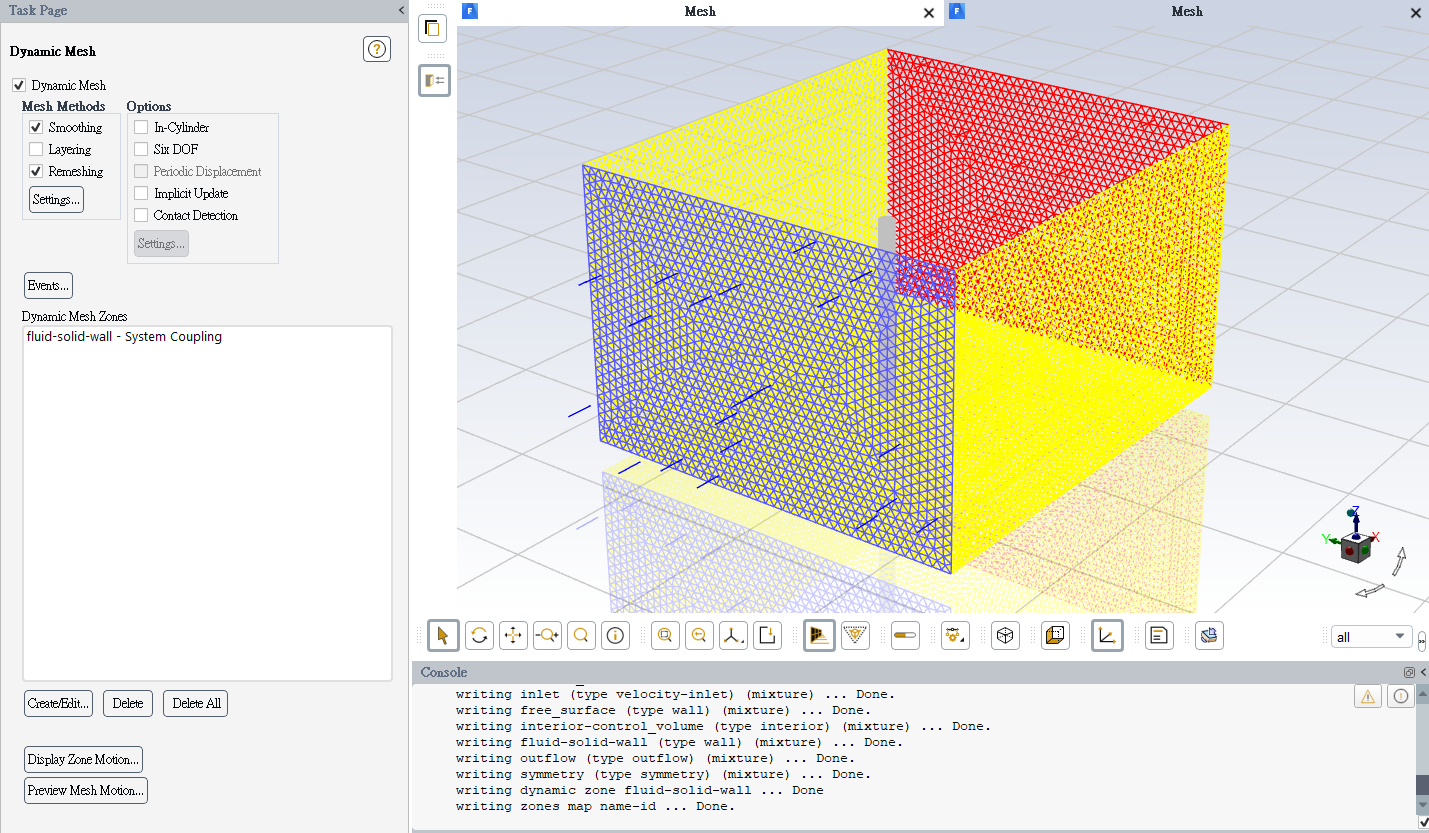
SubscriberG'day everyone,I'm a beginner conducting a CFD project on Karman Vortex Street, and I've been stuck with these settings for about 2 months. The most difficult part is the dynamic mesh since the cylinder will be forced by vortexes and oscillate in the CV (fluid domain). My questions are listed below:- The cells of the CV consist of hexa/prism+tetra(Multizone method); is Remeshing valid for this kind of mesh method?
- I only know that the "Fluid-solid-wall" should be set to "system coupling"; I don't know what I should assign for inlet, outflow, symmetry of 3 boundaries, and free surface. (stationary? or deformable?) Or just to set the CV deformable?
*note: "symmetry" indicates the faces of the boundary aren't physical walls; outside the boundary is still fluid.Hope someone can help me out, please...thanks. -
January 30, 2023 at 4:07 pm
Rob
Forum ModeratorIs the cylinder changing shape (bending) or moving as a rigid body? If it's bending can you use Fluent's FSI tool rather than coupling; if it's not bending it's pure 6DOF.
-
January 30, 2023 at 4:51 pm
Milne Ando
SubscriberHello,
in my study, its deformation isn't considered. Plus, I need to analyse the shear stress force and pressure force acting on its surface, so using Transient structural + Fluent is correct, right?
Sir, could you tell me the answers to my 2 questions in the content? Especially the second question, in the "dynamic mesh zone", should I assign something(stationary, deformable,...etc.) to the inlet, outflow, and symmetry? And what should they be assigned to respectively?
Looking forward to your reply. Thank you.
-
-
January 30, 2023 at 5:16 pm
Rob
Forum ModeratorOK, if there's no deformation you're moving the whole body based on the flow? How are you stopping the cylinder "escaping" from the model?
-
January 30, 2023 at 5:42 pm
Milne Ando
Subscriberyes, the rigid cylinder is forced by Kármán vortex street; this is "vortex-induced vibration". From what I know, the amplitude is quite small, so the cylinder won't escape from the control volume. Note that the flow moves toward the positive x-axis, and the cylinder has one DOF on the y-axis. It can't be washed away by the flow.
-
-
January 31, 2023 at 11:11 am
Rob
Forum ModeratorOK, so it's moving side to side. As it's only flow based, and not moving use the 6DOF solver with terms to prevent the cylinder moving too far: you don't need Mechanical for that part. Coming back to the motion, I'd move the cylinder and a block of mesh around it to preserve the boundary inflation and (probably) then remesh a zone around that block.
-
January 31, 2023 at 2:54 pm
Milne Ando
Subscriberhello,
yesterday, I tried a method similar to what you said above (use 6DOF to make the cylinder movable); in the "dynamic mesh zone", I simply assigned "rigid body" to "Fluid-Solid wall", and "deformable" to "CV". Unfortunately, the calculation stopped since negative cell volume occurred. Hmm...I'm sure that the time step size (0.25s) is small enough. The Strouhal number is 0.22; velocity is 0.02 (m/s); diameter is 25E-3 (m). Thus, the time step size should be less than 25E-3÷(20*0.22*0.02) which is around 0.284. Or maybe "Max iterations/Time step" was not enough? It was only 20. What should I do now?
Looking forward to your reply. Thank you.
-
-
January 31, 2023 at 3:08 pm
Rob
Forum ModeratorWhat's the cell size? You'll need a fine mesh on the cylinder to pick up shedding, and you'll also want to avoid that remeshing. The time step is based on the cell height, not the cylinder size. For efficient use of cpu you want to converge each time step in 10-15 iterations, the maximum to avoid solutions getting stuck on a time step, but also should mean all time steps converge.
-
January 31, 2023 at 4:14 pm
Milne Ando
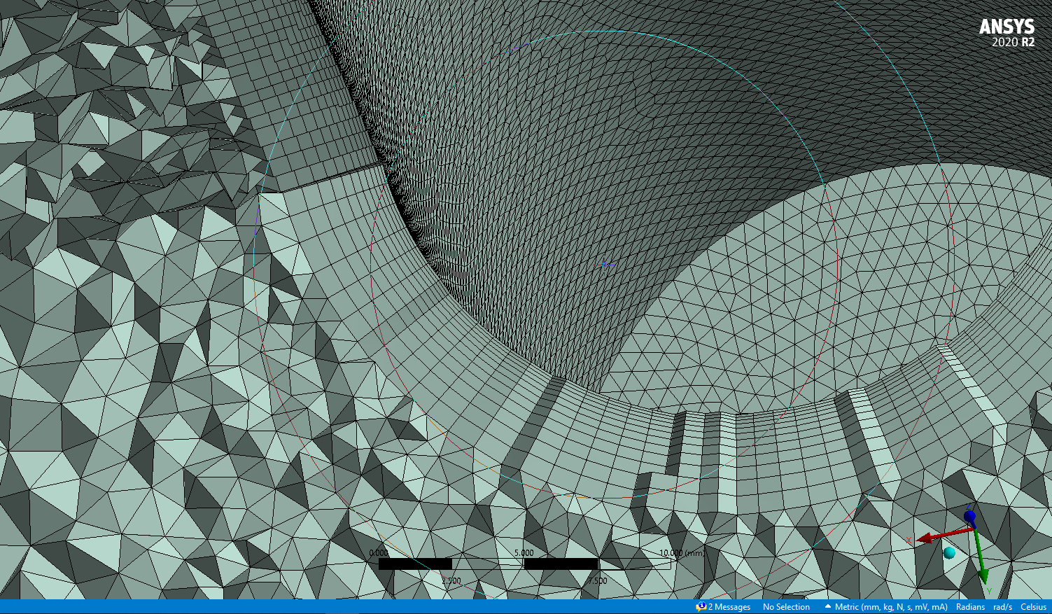
SubscriberThe mesh of the CV is quite good; the orthogonal quality of all cells is over 0.3. Face sizing is set to be 0.8 mm and used on the "Fluid-Solid wall". Inflation surrounds the "Fluid-solid wall" with a growth rate of 1.2, first layer height of 0.09 mm, and Maximum layers of 12. The transition between inflation and outer cells looks great as the pic shows. The element Size is 16.0 mm with a Max size of 24.0 mm.
Oh, I don't know that time step size is determined by cell height. Do you have an empirical formula for this?
-
January 31, 2023 at 4:34 pm
Rob
Forum ModeratorYou need to make sure the mesh motion can't pass through the cell in one time step. If you move the block of mesh around the cylinder it's safer.
-
February 2, 2023 at 10:51 am
Milne Ando
Subscriberhi,
I followed your hint: separating the inflation part from the CV and assigning "rigid body" to that cell zone; just as same as the user guide says. The CV is assigned to "deforming". Now time step size is 0.05s but negative cell volume was detected. How to see where the negative cells are?
-
-
February 2, 2023 at 11:52 am
Rob
Forum ModeratorIf the model is still "up" see if an adaption register for cell quality picks them up. If so, you can display that. Otherwise, it may be covered in the tutorials.
-
February 4, 2023 at 12:12 pm
Milne Ando
Subscriberokay, for those who have the same question, here is the conclusion:
to run a 3D FSI simulation, it's recommended to separate the inflation from the CV so that meshes of inflation can be preserved. Then in Dynamic Mesh Zones, set the inflation as "rigid body"; as for the CV excluding inflation, set it to be "deforming".
-
- The topic ‘3D FSI simulation (two-ways coupling), how to setup “dynamic mesh”?’ is closed to new replies.


- air flow in and out of computer case
- Varying Bond model parameters to mimic soil particle cohesion/stiction
- Eroded Mass due to Erosion of Soil Particles by Fluids
- Guidance needed for Conjugate Heat Transfer Analysis for a 3s3p Li-ion Battery
- Centrifugal Fan Analysis for Determination of Characteristic Curve
- I am doing a corona simulation. But particles are not spreading.
- Issue to compile a UDF in ANSYS Fluent
- JACOBI Convergence Issue in ANSYS AQWA
- affinity not set
- Resuming SAG Mill Simulation with New Particle Batch in Rocky

-
3862
-
1414
-
1221
-
1118
-
1015

© 2025 Copyright ANSYS, Inc. All rights reserved.


