TAGGED: apdl, transient-structural
-
-
January 26, 2023 at 11:59 pm
helen.durand
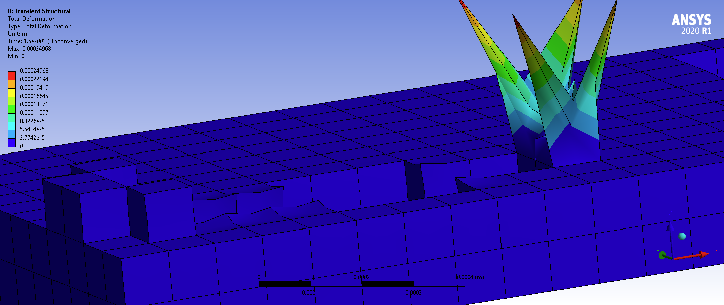
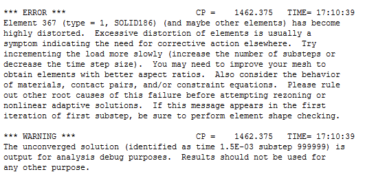
SubscriberHello, I am having issues with highly distorted elements. The simulation is a transient structural simulation that is getting temperatures from transient thermal. There is a fixed boundry condition on the bottom surface of the geometry. Elements are being added and removed using EKILL and EALIVE in APDL command blocks based on temperature. The material types are also being assigned based on temperature in the APDL code.
Below is an image of what is happening. I was wondering if anyone has ideas of why this is occuring?
Thank you!
-
January 27, 2023 at 12:08 am
peteroznewman
SubscriberTry to remesh with linear elements that have half the element size. The total number of nodes will be about the same, so the solve time will be similar, but linear elements might behave better than the quadratic elements you have.
You can also make the linear elements even smaller so that the hot spot that EKILL removes is at least four elements across instead of the one or three quadratic elements I see in the image above. That will take longer to solve, but might be more stable.
Anytime you have highly distorted elements, it is always important to make some edits under Analysis Settings, turn on Auto Time Stepping. You can configure that by Time Increment in seconds or Number of Substeps. The important point is to use much smaller Time Increments for the Initial and Maximum time steps so big time increments are avoided. You can allow the Minimum Time increment to be two orders of magnitude smaller to help the solver to converge each substep.
-
January 27, 2023 at 12:57 pm
SaiD
Ansys EmployeeHello,
Here is a video that you may find helpful: How to Handle Element Distortion Errors in Hyperelastic Materials — Lesson 3 - ANSYS Innovation Courses
The video uses a structural analysis that involves a hyperelastic material. But you may be able to find some helpful tips and tools for diagnosing and overcoming the excessive element distortion error.
Hope it helps.
-
January 30, 2023 at 10:39 pm
helen.durand
SubscriberThank you for the replies. Both were very helpful.
Some follow-up questions:
- Will using linear elements still allow me to get an accurate solution?
- In general, why would I choose linear elements over quadratic elements, or quadratic elements over linear elements?
- The elements in my simulation tend to have a large temperature gradient across them (one side of the element is significantly hotter than the other). Is this causing (or contributing to) the element distortion that I am seeing?
Thanks!
-
January 30, 2023 at 10:54 pm
peteroznewman
SubscriberTo maintain accuracy when changing Quadratic elements to Linear elements requires the element edge length to be less than half the size.
Smaller linear elements might converge where larger quadratic elements fail to converge. It’s possible that smaller quadratic elements will also converge.
Yes, the high temperature gradient is contributing to the element distortion. Smaller elements will reduce the temperature change across one element and shorter time increments will help the simulation to converge.
-
- The topic ‘Issues with highly distorted elements’ is closed to new replies.


-
4818
-
1587
-
1386
-
1242
-
1021

© 2026 Copyright ANSYS, Inc. All rights reserved.


