-
-
January 26, 2023 at 1:20 pm
Aboma Wagari Gebisa
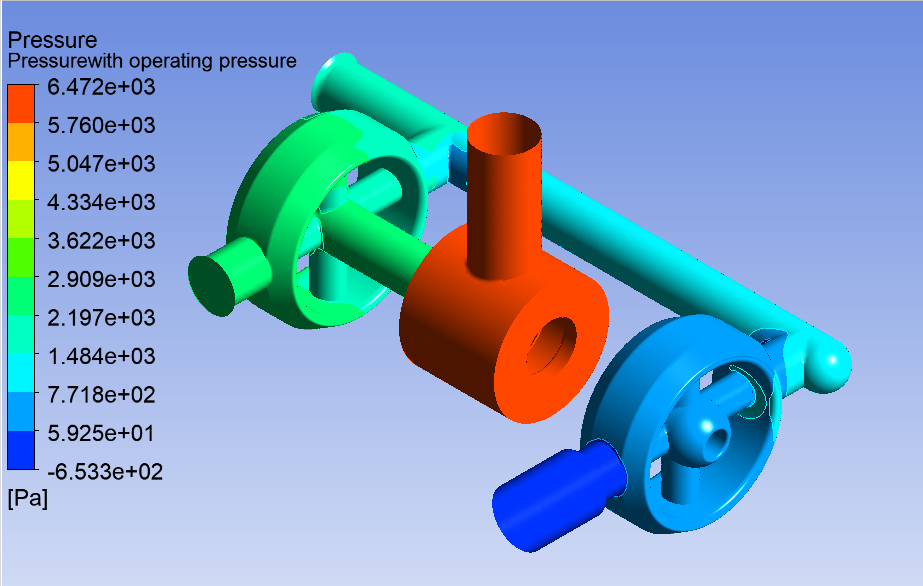
SubscriberI have a valve with the fluid volume shown in the picture below. I know the Inlet pressure, inlet temperature and volume flow rate (from which I can compute the velocity). When I use the pressure at the inlet as pressure inlet boundary condition, the CFD simulation could not converge. However, when I use the computed velocity as an velocity inlet, it converges. But the pressure contour values from this simulation show far lower values than the pressure at the inlet. My question here is, how can I relate the velocity inlet with the pressure inlet in my boundary condition? or is there a way I can relate the pressure contour with the inlet pressure on the simulation results when I used solely the velocity inlet as boundary condition? Thank you in advance for your assistance
-
January 27, 2023 at 2:04 pm
C N
Ansys EmployeeHello,
Could you please share the screenshot of the contour plots and also your boundary conditions.
Thanks
-
January 27, 2023 at 2:15 pm
Aboma Wagari Gebisa
SubscriberHello,
Thank you very much for your response.
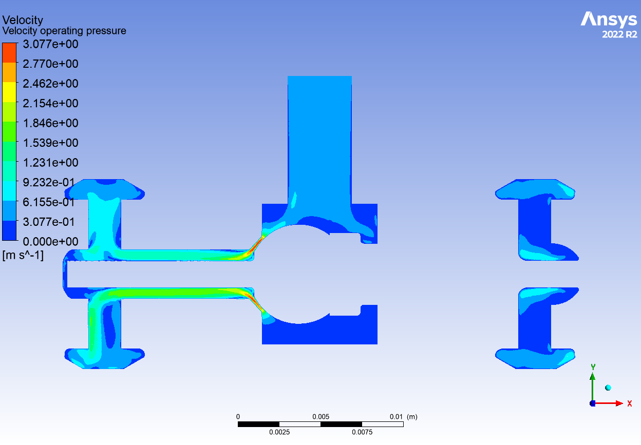
Below are both pressure and velocity contours.
My boundary conditions used for the simulation are velocity inlet of 0.508m/s. My pressure at the inlet is 34.47MPa. However, I couldn't enter this value when I use velocity inlet boundary condition.
Thank you again for your assistance.
-
January 30, 2023 at 6:21 am
Nikhil N
SubscriberHello,
"how can I relate the velocity inlet with the pressure inlet in my boundary condition?"
Whenever you define the pressure inlet boundary condition, be aware that the value you assign is the stagnation pressure and not the static pressure at the inlet. Using the equation of the stagnation pressure (depending on the type of flow), the code computes the velocity components using the static pressure from the previous iteration. So ultimately, it will behave like a velocity inlet condition but with some manipulation.
Thanks!
Nikhil
-
July 3, 2023 at 3:11 pm
Akbar Ravan Ghalati
SubscriberHi,
Thanks for the explanation.
Is it the same for Pressure Outlet BC? I mean Fleurnt calculates the velocity in the same way when we use Pressure Outlet BC?
-
-
January 30, 2023 at 6:25 am
Nikhil N
Subscriber"However, I couldn't enter this value when I use velocity inlet boundary condition"
When you assign velocity inlet condition, there is no need for the pressure value. However, when you assign pressure inlet condition, the solver will compute the velocity at the inlet. In either case, you can't define both.
-
February 1, 2023 at 11:54 am
Aboma Wagari Gebisa
Subscriber@Nikhil
I run the simulation based on your recommendation.
The simulation converges. The velocity contours show very big value compared to the the velocity I computed from the flow rate. In addition, when I check the absolute pressure contour, it shows higher value than the entered pressure at the inlet. I was expecting the maximum pressure to be the pressure inlet.
I am wondering why does that happen?
-
December 19, 2023 at 11:49 am
Niklas Melzer
SubscriberHello,I have a similar problem.I want to simulate a pipeline for my bachelor thesis and I know the initial pressure and the mass flow.How do I set the boundary conditions here?Thank you very much
-
- The topic ‘Pressure and velocity inlet boundary conditions’ is closed to new replies.


-
5094
-
1830
-
1387
-
1248
-
1021

© 2026 Copyright ANSYS, Inc. All rights reserved.


