TAGGED: pmsm
-
-
January 20, 2023 at 12:52 pm
Syed Kazmi
SubscriberHello, hope you are well.
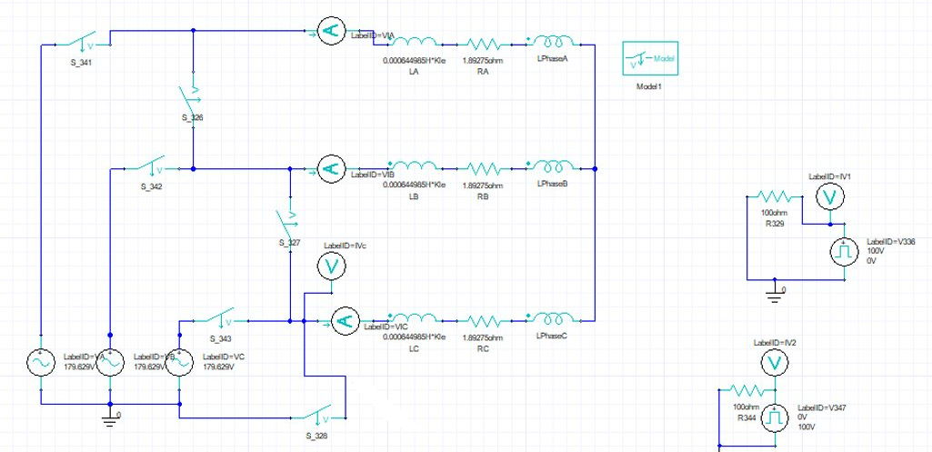
I am trying to evaluate a situation when a PMSM is running in open circuit generator condition and has a braking resistor also connected at terminal with switch between PMSM and generator still open.
At t=0 switch between braking resitor and terminals of the PMSM generator is closed.
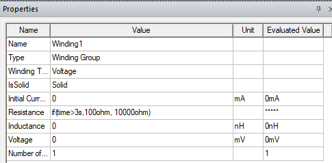
I want to see the currents in windings resulting from this close of switch and hence effects like demagnetisation resulting from such a braking and while doing this I want to vary braking resistor vlaues to see the effects of parametric sweep on demganetization of magnets.How can I do this?
In the advanced motor training on this platform, there are demag exercise examples, can those be somehow applied to my situation?
Looking forward to some pointers.
Thanks alot.
-
February 8, 2023 at 5:02 am
-
February 15, 2023 at 9:06 am
Syed Kazmi
SubscriberHi. thanks for the reply.
can you please elaborate a bit more on following points?
- When the switch of the braking resistor is open, will the winding be connected to a oltage source in externa circuit in maxwell? As per circuit theory, it should have a back emf source in open circuit and when the switch is closed for braking then that back emf should drive current in thw windings.
2. When external circuit is defined, how should the motion and excitation should be handled? I want that that rotor is rotating at some speed so there is induced emf in open circuit windings but when switch is closed, this will generate current in the windings and hence will brake the rotor also. How can i account for this chain of events in this simulation?
Best
Kazmi
-
February 23, 2023 at 4:25 pm
DELI
Ansys Employeehi,
no, the excitation will be either current, voltage or external, it will not switch from one to another. But you can setup the circuit design with switches, open braking resistor and switch to another voltage source.
Motion will be handled in motion setup in Maxwell design, it could run at constant speed or changing speed. And mechanical transient could be considered as well.
-
- The topic ‘PMSM braking with braking resistor’ is closed to new replies.


-
3567
-
1108
-
1063
-
1050
-
952

© 2025 Copyright ANSYS, Inc. All rights reserved.


