-
-
December 28, 2022 at 1:30 pm
jccubi
SubscriberDear colleagues, I need to constraint the plate panel edges straight and in parallel as shown in the following figure, when the plate is under a uniform line pressure in edges B3 and B2.
I had no problems with edges B1 and B2 but I was not able to do it in edges B3 and B4 as shown below.I used the following two constraint equations to move the corners C2, C3 and C4 in order to keep edges B3 and B4 in paralell.
However, I don´t know how to constraint nodes in edges B3 and B4 (except corners) to keep them in line with the corners.
I would appreciate some help on how to constraint nodes in B3 and B4 edges to keep them straigth and in parallel as shown in blue in the first figure. Thanks in advance. -
December 30, 2022 at 2:17 pm
-
January 3, 2023 at 2:22 am
jccubi
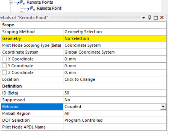
SubscriberThank you Ashish. Unfortunately, I tried your recommendation, but it did not work. In fact, I was not surprised because as far as I know coupled behavior means "same DOF solutions" but is clear from the picture above that edges B3 and B4 have not the same DOF except RZ. I also noted that in your picture DOF selection was left to "program control". I have tried that option and also the manual option with RZ active only, but the results are far from the expected (B3 and B4 straight and in parallel). Is there any other recommendation? Thank you
-
- The topic ‘Node Constraints Strategy’ is closed to new replies.


-
3862
-
1414
-
1220
-
1118
-
1015

© 2025 Copyright ANSYS, Inc. All rights reserved.


