-
-
December 19, 2022 at 2:32 pm
Farhad Hallaji Zahmatkesh
SubscriberHi all,
I used two link 180 elements as below (dotted lines). I applied temperature T1 on L1 and T2=-(L1T1)/L2 on line number 2 in order to have constant total length. After solving the code, I measured the strain in line 1 and 2 (ETABLE,starin, LEPTH, 1) and then calculated the final length. On the other hand, I measured the final length using LL1=sqrt(((nx(1)-(nx(4)+ux(4)))**2)+((ny(1)-(ny(4)+uy(4)))**2)) and LL2=sqrt(((nx(2)-(nx(4)+ux(4)))**2)+((ny(2)-(ny(4)+uy(4)))**2)) command lines. Althogh I only have thermal strain, the calculated final length with two mentioned approachs gave me different result! So, is there anyone who knows what is happening here?!
Â
-
December 20, 2022 at 1:35 pm
peteroznewman
SubscriberWhat were the two results?
-
December 20, 2022 at 1:45 pm
Farhad Hallaji Zahmatkesh
SubscriberThe initial length are L1=1414 mm and L2= 4123 mm (Sum=5537)
ETABLE,starin, LEPTH, 1 gives me 0.788 and -0.26 for link 1 and 2 starin respectively. So, the final length should be 2528 and 3009 mm for L1 and L2. (Sum=5537)
Also, after using LL1 and LL2 formulas to calculate the final length, the results are 3109 and 3146 mm. (Sum=6255)
Â
-
December 21, 2022 at 2:36 am
peteroznewman
SubscriberThe formula for the new lengths is
LL1 = CTE*(T1-T0)*L1+L1 and
LL2 = CTE*(T2-T0)*L2+L2
where T0 is the reference temperature for the initial link configuration. I assume the CTE is the same for both links.
Perhaps the reason for the error in the simulation result is that Large Deflection was not turned on for this solution. That means the solution was computed with the small rotation assumption, but the huge change in link length causes a large rotation in the link angles which invalidates the small rotation assumption. Rerun the solution with Large Deflection turned on and I expect you will get the expected link lengths.
-
December 21, 2022 at 7:54 am
Farhad Hallaji Zahmatkesh
SubscriberThank you Peter for your answer. I had turned on NLGEOM in my analysis.
I used CTE*(T1-T0)*L1+L1 to calculate the length after applying temperature and I presented the result in the second paragraph which are (2528 and 3009 mm).
The question is here:
Shouldn't these two formulas below give us the same result? I think they have to be same!
LL1 = CTE*(T1-T0)*L1+L1 (According to thermal strain)
andÂ
LL1=sqrt(((nx(1)-(nx(4)+ux(4)))**2)+((ny(1)-(ny(4)+uy(4)))**2)) (According to node's final position)
-
December 21, 2022 at 11:03 am
peteroznewman
SubscriberNo, those two formulas should not give the same result for your model.
The only way your formula would give the same result is in a different model where there is only one link with a fixed support on one end and is free on the other end.
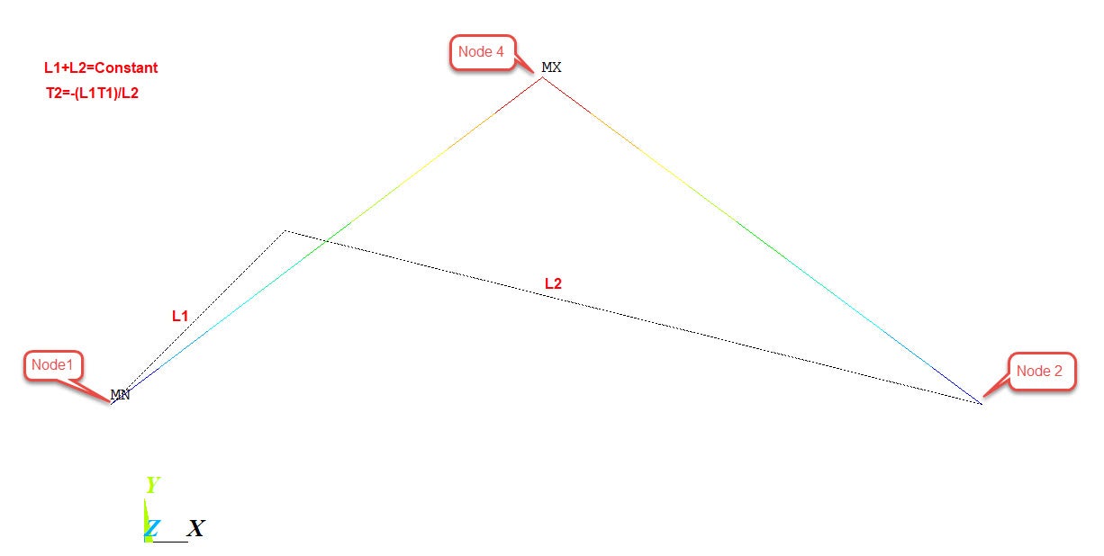
In your model ux(4) and uy(4) are functions of L1, T1, L2, T2 CTE, nx(1), ny(1), nx(2) and ny(2). In the different model I mentioned, there is no Link 2.
-
December 22, 2022 at 1:07 pm
Farhad Hallaji Zahmatkesh
SubscriberI don't agree with you. If we have mechanical strain in our structure, these two value should not be same, but here we only have thermal strain and node 4 is free to move in x-y plane.
-
- The topic ‘Strain in link180 element’ is closed to new replies.
-
5899
-
1906
-
1420
-
1306
-
1021
© 2026 Copyright ANSYS, Inc. All rights reserved.
