-
-
December 13, 2022 at 1:37 pm
Sergey Zhmaev
SubscriberHi,ÂI'm trying to simulate a simple setup of the PIN and BOX geometry for the ACME thread. I need to see how thread relief diameters are deformed both for PIN and BOX. Where ever I apply moment (torque) to the BOX geometry, it is just expending without catching any thread contacts. I also tried to flip faces and use PIN geometry for moment load, still the same it is just expending through the BOX and not seeing any contacts of the thread joint. Contact are Frictional contacts with 0,15 coefficient. See the image below. Here is a link to archive archive -
December 13, 2022 at 10:03 pm
peteroznewman
SubscriberSergey,
What version of ANSYS are you using? Is it the free Student edition or an unlimited license?
The first thread picks up most of the load and by the third thread, very little load is carried. If I understand the images, the outer shaft has a dark grey section that ends in a flat face which makes frictional contact with the flat shoulder face next to the green thread relief PIN section. The thread contact load path goes in a small loop from the shoulder face, up the outer tube to the first couple of threads, then down through the pin to the shoulder face again. This is where I expect to see the high stress. The much lower stress in the turquoise colour is due to the applied moment. I didn’t expect to see any stress in the threads at the right end. It’s behaving the way I expected, but apparently not the way you expected.
-
December 14, 2022 at 6:56 am
Sergey Zhmaev
Subscriber
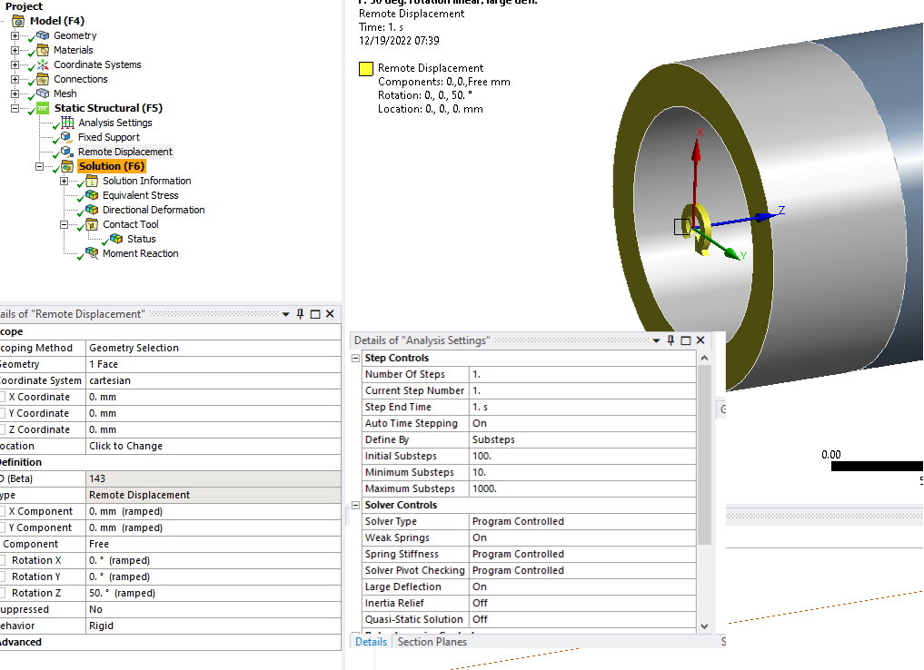
hi Peter. I have Mechanical 2021R2 license
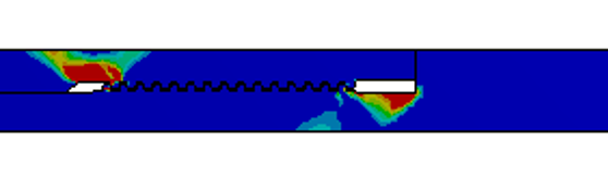
The real life testing of these two geometries shows necking of the BOX thread relief, in other words by torquing them BOX thread relief stretches very much. The thing I don't understand from FEA is why at the TRUE SCALE I see this picture (the part I apply moment to is just expending radially without seeing the other part).Â

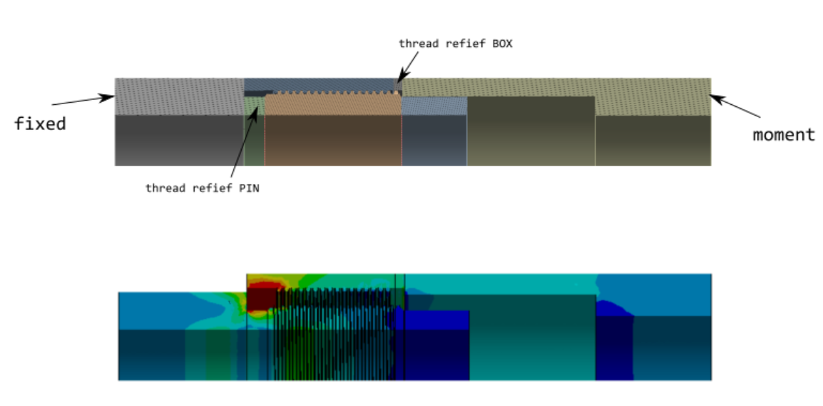
When I run 2D axisymmetric analysis and apply only axial force, the resulting picture is more realistic. See below. I'm expecting to see the similar image when I do 3D torque, since high torque generates axial force trying to neck both PIN and BOX thread reliefs.Â
-
-
December 16, 2022 at 11:15 am
peteroznewman
SubscriberUnder Analysis Settings, change the Large Deflection setting to ON and solve the model to see if the radial expansion effect goes away. Note that you might also have to change Auto Time Stepping to ON and set the Initial and Minimum Substeps to 10.
Yes, the 2D axisymmetric model with axial tension has a different stress pattern and is also what I would expect to see, but that is a different load to the moment.
-
December 19, 2022 at 6:40 am
-
December 19, 2022 at 1:09 pm
peteroznewman
SubscriberIn a Static Structural analysis, it is often better to apply a Displacement (or Remote Displacement) and measure the Reaction Force than it is to apply a Force or Moment and measure the Deformation. These two approaches are equivalent.Â
The reason it is better to apply displacement than force is that there must be a non-zero stiffness at each step of the process. When applying displacement, there is stiffness to ground and it is acceptable to have a zero force reaction. If you flip to the other approach and apply a force, there is no stiffness to ground and so no solution.
-
January 4, 2023 at 7:16 am
Sergey Zhmaev
SubscriberÂ
Hi again
I’m getting back to this question I created for the toque calcs.
Does anyone know how I can simplify this 3D analysis to 2D? Is it possible at all, or it must be 3D for accurate results?
Can I torque 2 pieces (male, female) using 2D analysis?Â
Â
-
January 4, 2023 at 5:25 pm
peteroznewman
SubscriberA thread is 3D and you can rotate it to preload the threads. You could make a 2D version that has rows of slots, but it's difficult to pretension that.
-
- The topic ‘ACME thread torque’ is closed to new replies.
-
6374
-
1906
-
1457
-
1308
-
1022
© 2026 Copyright ANSYS, Inc. All rights reserved.


