-
-
December 6, 2022 at 1:21 pm
javier.medina.galera
SubscriberHi, I would like to model a tapered beam forming a hollow conical geometry as a transition piece between two cylinders of different diameter. I need it to be a beam type for further calculations in Aqwa.
I'm aware that with APDL you can create a tapered cross section and then assign it to a line. Is there any way to do this in Design modeler or Space claim? Can I run the APDL code inside DM or SC??
Thank you very much.
-
December 6, 2022 at 2:59 pm
ErKo
Ansys EmployeeHi
You can not do that.
It is only possible to define the tapered beam inside mechanical using APDL command snippet.
Never done this but perhaps it is possible (see the help manual for tapered beam, e.g., sectype,3,taper, sectype,2,beam, and sectype,1,beam, etc)
All the best
Erik
-
December 6, 2022 at 5:55 pm
Ankush Choudhary
Ansys EmployeeHi Javier,
Spaceclaim, Design Modeler, and Mechanical Gui do not support the tappered beam section. For defining the tapered section, you need to insert the APDL script inside the mechanical.
Thanks,
Ankush
-
December 9, 2022 at 3:30 pm
javier.medina.galera
SubscriberHi Erik and Ankush,
Thank you very much for your answers. I've tried to follow your advice but I'm stuck, I'm not familiar with working with snippets or running scripts inside mechanichal so I may be missing something.
I've written this APDL script that generates my desired geometry:
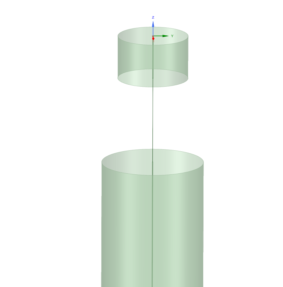
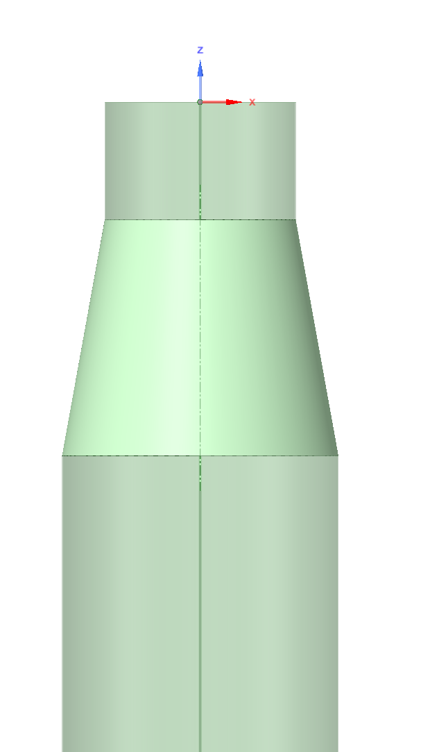
FINISH/CLEAR ! clear database/PREP7 ! enters the preprocessor! MATERIAL PROPERTIESYNGMOD = 2e11 ! Young's modulusPCOEF = 0.27 ! Poisson coefficientMDENS = 7850 ! Material density! SECTION DIMENSIONS! CTUBE1Intrad1 = 6470Extrad1 = 6500!CTUBE2Intrad2 = 9370Extrad2 = 9400! Element typesET,1,BEAM189 ! create 3-node beam elementET,2,SHELL281!define materialMPTEMP,,,,,,,,MPTEMP,1,0MPDATA,EX,1,,YNGMOD ! Young's modulusMPDATA,PRXY,1,,PCOEF ! poisson coef.MPDATA,DENS,1,,MDENS ! Density. For considering own weight! Keypoints DefinitionK,1,0,0,0K,2,0,0,-4000K,3,0,0,-12000K,4,0,0,-120000K,5,0,0,10000SECTYPE,1,BEAM,CTUBE,CT,0SECOFFSET, CENT ! Origin of section located at CoG of sectionSECDATA,Intrad1,Extrad1,64,0,0,0,0,0,0,0,0,0 ! Variables of sectionLSTR,1,2! Straight line connecting each KPLSEL, , , , 1 ! Selecting the generated lineLATT,1, ,1, , , ,1 ! Assigning the variable section, element type and material properties to lineLESIZE,1,400 , ,, , , , ,1 ! Size of MeshLMESH, 1 ! Line MeshingSECTYPE,2,BEAM,CTUBE,CT,0SECOFFSET, CENT ! Origin of section located at CoG of sectionSECDATA,Intrad2,Extrad2,64,0,0,0,0,0,0,0,0,0 ! Variables of sectionLSTR,3,4! Straight line connecting each KPLSEL, , , , 2 ! Selecting the generated lineLATT,1, ,1, , , ,2 ! Assigning the variable section, element type and material properties to lineLESIZE,2,800 , ,, , , , ,1 ! Size of MeshLMESH, 2 ! Line MeshingLSTR,2,3! Straight line connecting each KPSECTYPE,3,TAPER, ,TC ! We define a taper to generate a variable section. Tower's transition piece.SECDATA, 1 ,0,0,-4000, ! Initial base of variable sectionSECDATA, 2,0,0,-12000,LSEL, , , , 3 ! Selecting the generated lineLATT,1, ,1, , , ,3 ! Assigning the variable section, element type and material properties to lineLESIZE,3,400 , ,, , , , ,1 ! Size of MeshLMESH, 3 ! Line Meshing! Upper sectionK,5,0,0,10000LSTR,1,5! Straight line connecting each KPLSEL, , , , 4 ! Selecting the generated lineLATT,1, ,1, , , ,1 ! Assigning the variable section, element type and material properties to lineLESIZE,4,1000 , ,, , , , ,1 ! Size of MeshLMESH, 4 ! Line Meshing/ESHAPE,1.0And the result is
Actually, the part of the code I would like to implement is this, where I define a tapered section from the sections already defined above for the rest of the line bodies:
LSTR,2,3! Straight line connecting each KPSECTYPE,3,TAPER, ,TC ! We define a taper to generate a variable section. Tower's transition piece.SECDATA, 1 ,0,0,-4000, ! Initial base of variable sectionSECDATA, 2,0,0,-12000,LSEL, , , , 3 ! Selecting the generated lineLATT,1, ,1, , , ,3 ! Assigning the variable section, element type and material properties to lineLESIZE,3,400 , ,, , , , ,1 ! Size of MeshLMESH, 3 ! Line MeshingWhat I've tried so far:
- Use design modeler to build the line bodies and the two CTUBES, transfer the geometry to a mechanichal model (tried to implement the snippet by inserting an apdl command to the desired line body, but it doesn't make any change) and then to the hydrodynamic diffraction module.
- Archive the apdl model and load it in workbench using the external model option, but workbench is reading the the tapered section as a constant CTUBE equal to the start of the tapered section
- Use the spaceclaim 'extract' option under 'prepare' tab to extract the tapered section, but the hydrodynamic difraction doesn't like it
I would really apreciate if you could help me implementing the code inside mechanichal. Thank you very much for your help.
Best regards,
Javier
-
December 9, 2022 at 4:15 pm
ErKo
Ansys EmployeeHi
Have not used this much and it is not really convenient.
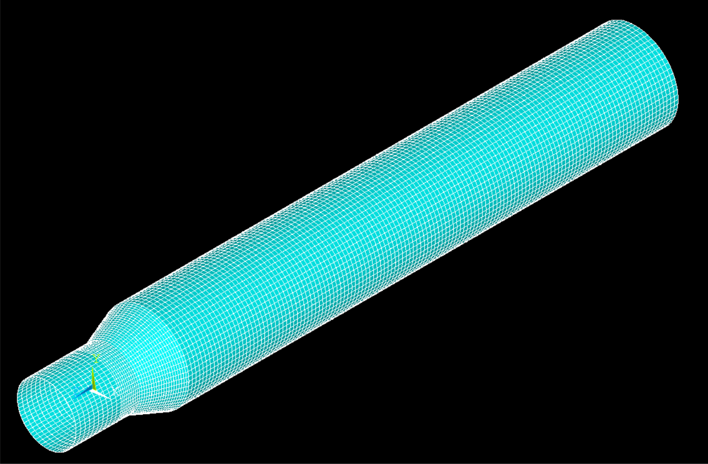
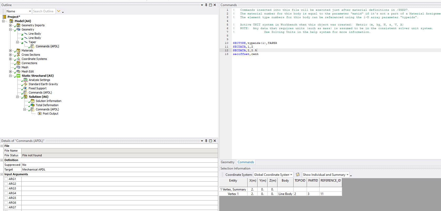
So the way to use it in WB / mech. (define 3 line bodies/geom., and then change the section of the taper as shown in the apdl command snippet placed under it in the tree below).
We can not view it (taper) in mechanical ui – so only way is in APDL (used an image to view it – see below)
The last snippet is:
/eshape,1,ON
/SHOW,png
EPLOT
/show,close
-
- The topic ‘How can I model a tapered cross section beam?’ is closed to new replies.


-
4858
-
1587
-
1386
-
1242
-
1021

© 2026 Copyright ANSYS, Inc. All rights reserved.


