TAGGED: #multiphase_models, cfd-convergence, convergence, fluid, open-channel
-
-
November 2, 2022 at 10:06 am
pv00170
SubscriberI am performing a multiphase 2D open-channel flow using air (primary phase) and water (secondary phase).
- The thing is that residuals never converge even if I change the mesh. And if they seem to converge, drag coefficient vary sustanciably (60% variations aprox.)
-
November 3, 2022 at 9:43 am
Rob
Forum ModeratorFor the graphics, in 2d don't pick any surfaces. You'll get a continuous contour as the solver will magically figure it out.
I can't tell if you have supports under the bridge, remember in 2d there's no way for the water to get around these: that could cause some interesting results. If they're buoyant cells that may be different.
Residuals & reports are mostly as expected. You may need to resolve the mesh near the free surface, but I can't see from the image. Generally in multiphase there is something in the flow (reflected waves, ripples etc) that are transient. The question you need to consider is whether these waves etc are altering the data you're interested in. Ie are you wanting to see the flow field and understand the range of drag, or see the speed/rate of any transient effects?
-
November 3, 2022 at 12:15 pm
pv00170
SubscriberDo you mean with the first sentence to pic Fluid for the contours rather than Internal? (I don’t know why there is such high velocity under the bridge slab deck)
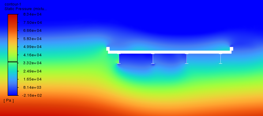
In this case I am not considering the supports as I am analysing middle span sections. (The four thin small lines below the deck are steel girders).
Does Fluent consider buoyancy?
Then, Residuals & reports are like this even though is a steady state?
-
-
November 3, 2022 at 1:31 pm
Rob
Forum ModeratorYes, pick fluid. It's a change on older versions as you didn't pick anything up until a couple of releases back.
BOI is fine, adaption is another option.
Lastly, the acceleration is because you're forcing water through a smaller gap: where else will it go in a 2d model?
Fluent considers buoyancy for fluids, depending on density and if you turned gravity on. Solids would need moving mesh (or immersed boundary) and some other settings to be buoyant. The first example we had was a cube hitting water, then a lifeboat (getting off oil & gas platforms isn't that easy if it's on fire) and now things falling off aeroplanes https://www.youtube.com/watch?v=v0oTru6qUXU
-
November 3, 2022 at 2:23 pm
pv00170
SubscriberYeah, I understand why acceleration is happening. Makes sense.
Is the dynamic mesh for the interface or for the bridge?
The thing is that the bridge is a void area, therefore it cannot move. If it is designed like this, is buoyancy still considered?
In this analysis I just want to get drag and lift coefficients, but since values were varying a lot for a steady state, I don't know if the simulations is performed correctly. (I would understand if values are sinusoidal ish for transient states.
-
-
November 3, 2022 at 4:06 pm
Rob
Forum ModeratorDynamic mesh would be if the bridge was moving. You can probably assume it's fixed, but may want to google Tacoma Narrows Bridge Collapse for when that's not case! It'll only move if you tell it to, so at present it's not going anywhere.
We often talk about "dynamic adaption" which refers to automatic mesh refinement & coarsening. That's commonly used around a free surface to refine the mesh as the surface moves. As you've not got any waves it's probably not necessary.
The only issue with the set up (that I can see) is that the bridge supports are effectively continuous so the water can't go around them. I don't know if that's part of the design but in most cases they probably shouldn't be there.
Drag etc will almost certainly vary with time, in the steady solver it can vary with iteration if the solver can't lock the flow down to a single converged solution. You either need to run transient, or take the steady result with some scatter due to inherent transients in the flow: that's something you may want to discuss with your supervisor.
-
November 3, 2022 at 5:44 pm
pv00170
SubscriberWhat is seen in the immage are not supports, are girders. It is a cross section. In this case no pier are modelled so water is flowing under the deck.
Is there any way to obtain the percentage/quantity of the pressure on the void (solid) due to buoyancy or I have to do it by hand?
PS: Thanks a lot for your help
-
-
November 4, 2022 at 9:37 am
Rob
Forum ModeratorThere are force reports on walls, along with volume reports to find out how much air is trapped under the deck.
-
November 4, 2022 at 10:05 am
pv00170
SubscriberWhen I do florce reports on walls I check drag and lift forces.
But lift forces I assume to be due to hydrodynamic, buoyancy forces and weight of water above the bridge deck.
Is there any direct way to obtain the forces of each of these sources? Like:
- Hydrodynamic - 20000 N
- Buoyancy: +30000 N
- Weight of water: -1000 N
-
-
November 4, 2022 at 10:19 am
Rob
Forum ModeratorThe solver doesn't know the mass of the bridge, so pressure etc is a function of the water and air volume density in the trapped pockets. If you look there are also forces (x, y & z) as opposed to lift & drag.
-
November 4, 2022 at 12:35 pm
pv00170
SubscriberYeah I get the solver doesnt know the mass of the bridge, but knows the volume of displaced water, and I imagine it solves buoyancy by using it. I assume there is no direct method to check wich % of the total pressure are due to water weight, buoyancy and hydrodynamic.
With "If you look there are also forces (x, y & z) as opposed to lift & drag" do you mean negative values?
-
-
November 4, 2022 at 10:36 am
pv00170
SubscriberYeah I get the solver doesnt know the mass of the bridge, but knows the volume of displaced water, and I imagine it solves buoyancy by using it. I assume there is no direct emthod to check wich % of the total pressure are due to water weight, buoyancy and hydrodynamic.
With "If you look there are also forces (x, y & z) as opposed to lift & drag" do you mean negative values?
-
November 4, 2022 at 2:33 pm
Rob
Forum ModeratorThe solver knows the flow and composition, so can find the forces on walls. That isn't broken down by cause.
The forces are what the fluid exterts on the walls, so yes, negative would probably be correct. However, as the bridge has no mass the results may be misleading.
-
November 4, 2022 at 3:47 pm
pv00170
SubscriberI will use 2D CFD results in a 3D FE analysis in which bridge has mass. Then, I will check if drag and lift forces can move the bridge.
Do CFD results vary depending on the mass of the bridge? How can this mislead the results? (Could you explain more, since maybe there is something I am missing)
-
-
November 4, 2022 at 3:52 pm
Rob
Forum ModeratorThe bridge is fixed so won't do anything in the Fluent solver. Have a look at what Mechanical takes in as boundary conditions, I very much doubt it's lift and drag over the components.
-
November 4, 2022 at 4:02 pm
pv00170
SubscriberI use in the FE analysis: earth gravity for the bridge, fixed/non-fixed supports (depending on the bearings) and imported pressure on the bridge faces (walls) from fluent.
-
November 25, 2022 at 2:18 pm
pv00170
SubscriberHi Rob, I have another question. When I simulate high velocity (10 m/s) for let's say 5.5 m height water, I get weird results.
Density after initialization (red water, blue air):
Velocity after initialization (10 m/s for the water 0 m/s for the air):
After a lot of iteration water interacts with the structure, but a weird wave is created upwards as seen in the following pictures. Therefore, water height ends up being greater than specified in the inlet. It ends up being like this (not finished running simulation):
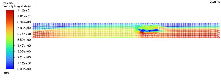
Also, the velocity in front of the structure is reduced from 10 to 7 … Drag and lift coefficients are still computed with a velocity of 10 m/s but I don’t think this results are right…
-
-
November 25, 2022 at 3:25 pm
Rob
Forum ModeratorLooks like the water can't get under the bridge quickly enough so builds up. Have a look at flooding around bridges: it's an irregular problem!
-
November 29, 2022 at 8:53 am
pv00170
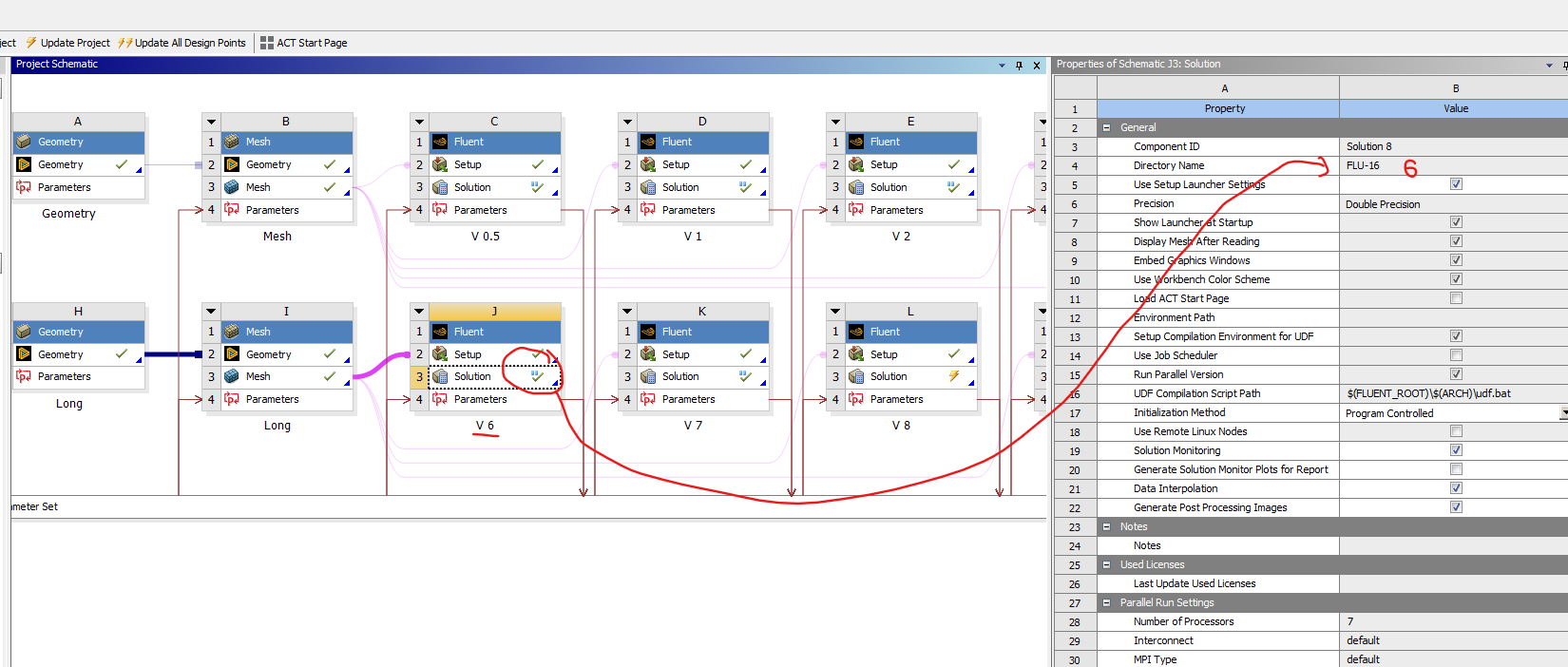
SubscriberAlso, I have many files and solutions. Normally I run the simulations and then I ectract the resutls from the directory name folder. Is there any way I can change the name of it? Because when I enter in the folder I always have to check which FLU folder is for Velocity 6 (V 6) whereas I would like it to be saved in FLU-6
The thing is that as I deleted previous FLUENTs, directory names were adding in number.
-
November 29, 2022 at 9:37 am
Rob
Forum ModeratorIn Workbench you can't rename files, that would interfere with the project workflows. If you run Fluent outside of Workbench you can. You can also export case & data from Fluent in WB to use externally.
-
December 1, 2022 at 1:26 pm
pv00170
SubscriberThank you Rob, on the other hand, when I import AutoCad files to Spaceclaim, lines are properly transfered whereas surfaces and bodies are transfered but in a small scale.
Normally they are transfered in inches whilst I work in meters (I use meters also in AutoCad).
Default units in AutoCad and Spaceclaim are both in meters, just when I import the file it turns to inches. Let's say I have a surface of 70mx11m in Autocad. Then when I import it becomes 70inx11in.
-
-
December 1, 2022 at 1:38 pm
Rob
Forum ModeratorThat'll be AutoCAD, the export functions have always been a little "different": it's not that long ago (OK, 30 years) that it didn't even have surface tools. Just mesh whatever you get and use the Scale function in Fluent to get back to metres.
-
December 1, 2022 at 2:38 pm
pv00170
SubscriberIs there any way to Scale it from inch to meters, or do I have to do it numerically (putting numbers I mean)
I did it before but I had to calculate the number to scale it.
-
-
December 1, 2022 at 2:42 pm
Rob
Forum ModeratorIn the Scale panel look to the right hand side. Ansys is an American company so we have to be able to easily convert from inches....
-
December 16, 2022 at 5:43 pm
pv00170
SubscriberHi Rob, I have another question. This time is about pressures: static and dynamic pressures.
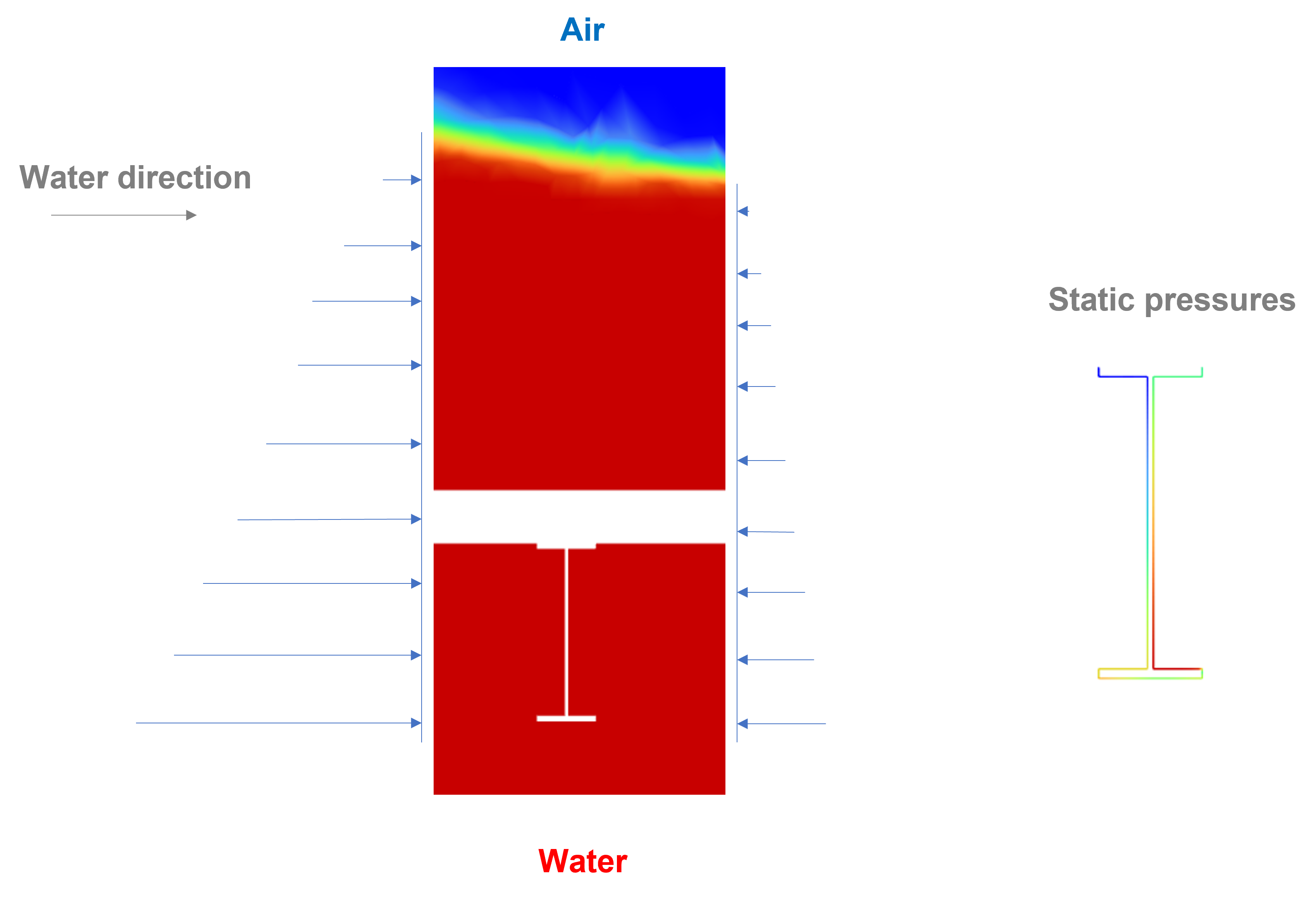
I have checked some results and I quite don't understand this: static pressure is merely due to the column of water above the analysed cell. Therefore I assume that higher water column higher static pressures, but this is not the case when I check pressures, please see the image below.
Here the water column is higher on the left part of the "I" section than the right side. Still pressures are higher in the right side than the left one. I think I am missing something related how static pressures are estimated.
As far as I understand, dynamic pressure is calculated at the walls by using the velocity next to the cell.
And static pressure is due to gravity as follows;
-
December 16, 2022 at 5:52 pm
-
-
January 3, 2023 at 12:02 pm
Rob
Forum ModeratorStatic pressure is not the same as hydrostatic pressure, the latter is what you're asking about and is due to the mass off stuff above the location.
-
January 9, 2023 at 12:26 pm
pv00170
SubscriberTrue, thank you Rob.
Is the definition of static pressure the one given above?
Is there any place where I can find more information on how this static pressure is defined in fluent?
-
-
January 9, 2023 at 1:37 pm
Rob
Forum ModeratorIt should be covered in the documentation, the field variable chapter.
-
January 19, 2023 at 1:06 pm
pv00170
SubscriberHi Rob, do you know if it is possible to import CFD results on Explicit Dynamics?
I want to do an EKILL analysis and I have read that it is easier in Explicit Dynamics rather than Static Structural using APDL commands.
The problem is that when I try to import CFD results by dragging from "fluent - solution" to "Explicit Dynamics - Setup" i am not able to drag it.
-
January 19, 2023 at 1:30 pm
Rob
Forum ModeratorNot sure, and the person I usually ask about Mechanical doesn't know either. However, he did say that ekill was built into Static Structural so no need to use APDL.
-
January 19, 2023 at 1:35 pm
pv00170
SubscriberI have seen there is an EKILL built in Static Structural which can be modelled to supress elements at a certain step.
Does he know if there is an EKILL built in Static Structural which deletes cells if stress or strain is above a certain value?
-
-
January 19, 2023 at 1:46 pm
Rob
Forum ModeratorNo idea. I can use Mechanical, but only because it's the same interface as the older meshing tool. You may be better off adding a thread into Mechanical section.
-
January 25, 2023 at 6:08 pm
pv00170
Subscriber.
-
February 17, 2023 at 9:17 am
pv00170
SubscriberGood morning, I have another question and is regarding residuals.
I am checking the drag coefficient, and I thought maybe to use a convergence condition of the drag by defining a stop criterion of 1e-05 and use iterations 5.
If I apply this, convergence condition of the drag coefficient is met with continuity residual around 1e-03. As far as I have heard, a residual of 1e-05 would be a “nice” one. But the convergence condition is met before, is it okay to stop the iterations of this time step when the convergence condition is met (continuity residual 1e-03) or should I wait for residuals to reach continuity residual 1e-05?
I mean, am I loosing too much “reality” by stopping the time step when drag coefficients criteria are met?
-
-
February 17, 2023 at 10:20 am
Rob
Forum ModeratorPlease post into a new thread.
-
February 17, 2023 at 10:55 am
pv00170
SubscriberDone in
/forum/forums/topic/use-of-convergence-condition-vs-residuals-cfd/
Thank you
-
-
March 28, 2023 at 12:36 pm
pv00170
SubscriberDear Rob,
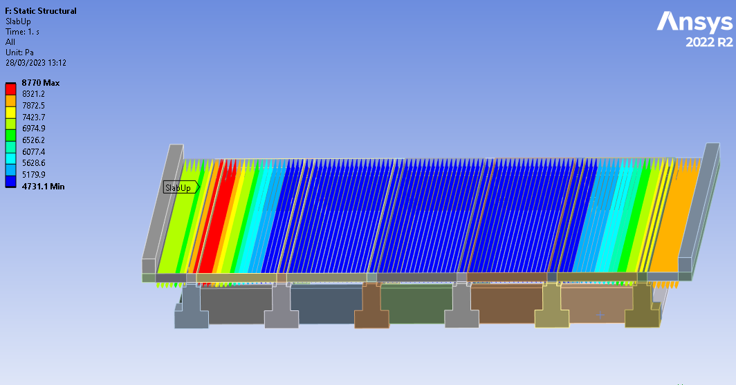
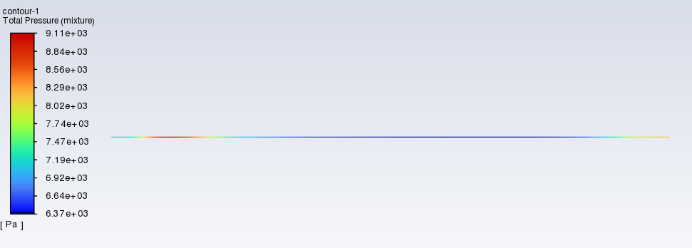
When I export CFD pressures from Fluent to Static Structural or Transient Structural only static pressures are imported (therefore no dynamic ones).
What can I do to import total pressures (dynamic and static).
In the first picture there's the imported pressures in Static Structural (which correspond to the static pressures obtained in fluent) whereas in the second, the total pressures obtained in CFD.
-
March 28, 2023 at 1:34 pm
Rob
Forum ModeratorPlease post a new thread - I don't do much with the FSI part of the code so don't know what's passed.
-
- The topic ‘Results not converging in open channel flow’ is closed to new replies.


- air flow in and out of computer case
- Varying Bond model parameters to mimic soil particle cohesion/stiction
- Eroded Mass due to Erosion of Soil Particles by Fluids
- I am doing a corona simulation. But particles are not spreading.
- Centrifugal Fan Analysis for Determination of Characteristic Curve
- Guidance needed for Conjugate Heat Transfer Analysis for a 3s3p Li-ion Battery
- Issue to compile a UDF in ANSYS Fluent
- JACOBI Convergence Issue in ANSYS AQWA
- affinity not set
- Resuming SAG Mill Simulation with New Particle Batch in Rocky

-
4067
-
1487
-
1308
-
1156
-
1021

© 2025 Copyright ANSYS, Inc. All rights reserved.


