
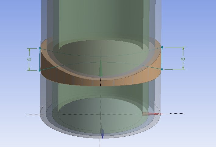
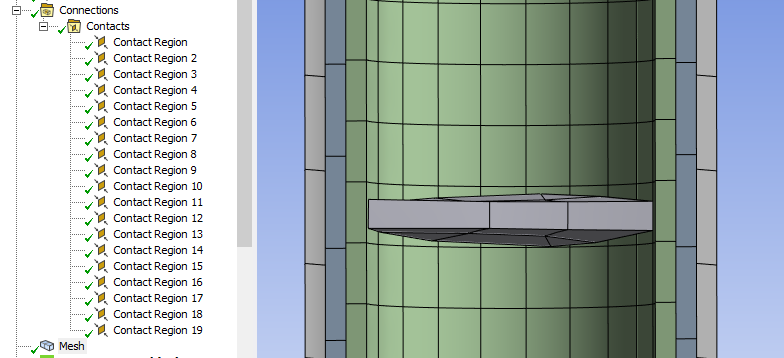
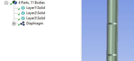
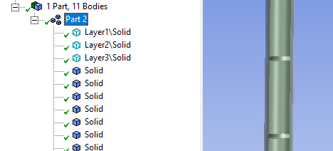
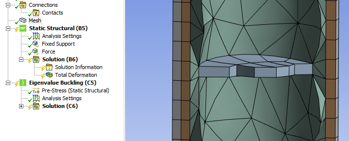
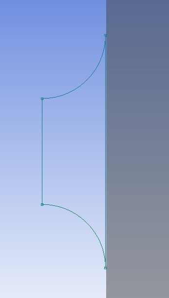
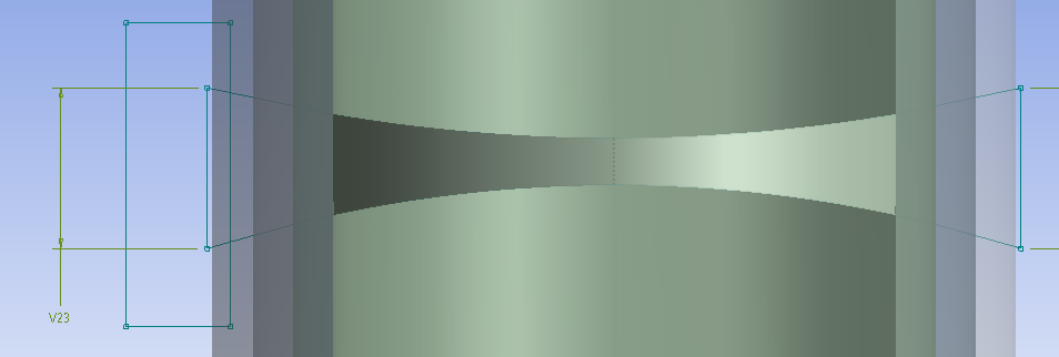
Splitting the geometry and assigning different material property for each layer


Viewing 34 reply threads
- The topic ‘Splitting the geometry and assigning different material property for each layer’ is closed to new replies.


