-
-
September 15, 2022 at 2:15 pm
LaraDlg
SubscriberHi,
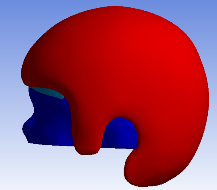
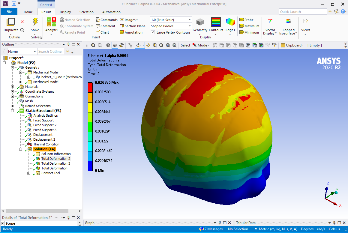
I've been struggling with the simulation for a while, trying multiple combinations of the contact parameters to reduce the penetration between 2 objects but now that the penetration is reduced, the target surface appears very bumpy (what I assume is artefact) but because of that I can't re-use the mesh in another simualtion.
my contact is frictional (you can imagine a head growing in a partly restrictive helmet) some areas are already in contact when the heead starts growing. The parameters I've defined so far are:
1) detection method: pure penalty
2) small sliding: off
3) Normal stiffness: 1
4) interface treatment: adjust to touch
I've tried changing the pinball radius but it only increases the simulation time (so far around 14 hours)
Any ideas or suggestions are very welcome!
Thanks :)
Lara
-
September 15, 2022 at 2:26 pm
peteroznewman
SubscriberHi Lara,
Seeing some images of the geometry and the contact pressure plot would be helpful.
Have you tried using Linear elements instead of Quadratic elements?
Regards,
Peter
-
September 15, 2022 at 2:52 pm
-
September 15, 2022 at 3:22 pm
-
September 15, 2022 at 3:55 pm
LaraDlg
Subscriberyes, I've checked, it's already set to 1 - true scale
Best wishes,
Lara
-
September 17, 2022 at 6:42 pm
LaraDlg
Subscriber@peteroznewman I tried changing the elements order but it results in more singularities in the deformation
-
September 17, 2022 at 8:15 pm
peteroznewman
SubscriberHi Lara,
What version of ANSYS are you using?
I am willing to take a look at your model if you are willing to share the .wbpz archive file through a file sharing site such as Google Drive, Dropbox or Jumpshare, which is what I use. Keep the archive file size small by clearing the mesh and save without results.
-
September 18, 2022 at 12:21 pm
LaraDlg
SubscriberHi Peteroznewman,
I'm using the 2020 R2 version.
The last simulation I ran failed but I can send you the file via One Drive, that would be great!
Many thanks,
Lara
-
September 18, 2022 at 2:18 pm
peteroznewman
SubscriberHi Lara, I have ANSYS 2020 R2 so go ahead and leave a link to the .wbpz archive file saved in on One Drive.
-
September 18, 2022 at 2:20 pm
peteroznewman
SubscriberHi Lara,
I have 2020 R2 so please reply with a link to the .wbpz archive file saved on your One Drive.
Regards,
Peter
-
September 18, 2022 at 3:09 pm
LaraDlg
SubscriberHi Peteroznewman,
Here you go :
Let me know if it works!
Lara
-
September 18, 2022 at 5:03 pm
peteroznewman
SubscriberHi Lara,
I opened your archive and opened System C: next follow up ... and started meshing that. Will it successfully mesh from a Generate Mesh command?
Peter
-
September 18, 2022 at 5:10 pm
LaraDlg
SubscriberHi Peter,
In my experience, you need to get the mesh ready and then solve the whole thing but it takes a long time! I still have some penetration in the system C but the artefact is not as bad as than in the system F
-
September 18, 2022 at 5:32 pm
peteroznewman
SubscriberHi Lara,
Yes, I also like to get the mesh ready first, but sometimes, with a multibody part, I need to help the mesher by meshing bodies in a specific order that Generte Mesh doesnt follow and that causes the mesh to fail, but if I do it in my order, it succeeds.
I will look at system F first.
-
September 18, 2022 at 6:48 pm
LaraDlg
SubscriberHi Peter,
that's good to know, thanks!
-
September 19, 2022 at 1:41 am
-
September 19, 2022 at 10:49 am
LaraDlg
SubscriberHi Peter,
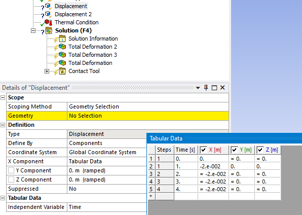
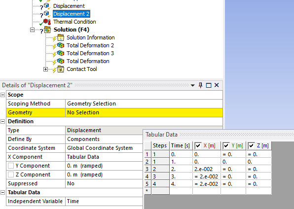
Displacement 1 is the front part of the helmet (-20 mm) and displacement 2 is the back part (20 mm)
-
September 19, 2022 at 2:30 pm
peteroznewman
Subscriber -
September 19, 2022 at 2:37 pm
LaraDlg
SubscriberHi Peter,
the rough contact (also works with frictional) is the contact between both parts of the helmet when it closes around the head (the contacts corresponds to each cross sections, the front part being the target).
I'm running a new simulation on system C witht the contact stiffness updated at eah iteration and I'm now adjusting the pinball radius to avoid the singularities but there is much less penetration.
However the system C was easier to solve than the F so I don't know if these parameters will still work.
Lara
-
September 19, 2022 at 2:53 pm
-
September 19, 2022 at 2:58 pm
LaraDlg
SubscriberHi Peter,
you're right, I had defined a contact for a trial where the helmet parts were made of several parts each and just never changed it. You don't need the rough contact in this case indeed sorry!
Lara
-
September 19, 2022 at 7:58 pm
peteroznewman
SubscriberHi Lara,
System F is solving using the PCG Iterative Solver. The analysis setting is Program Controlled. Did you ever try setting it to use the Sparse Direct solver?
Peter
-
September 19, 2022 at 8:07 pm
LaraDlg
SubscriberHi Peter,
No I've never tried it, I'm not familiar with the solver controls. I'll look into it!
Lara
-
September 20, 2022 at 10:51 am
peteroznewman
SubscriberHi Lara,
I let the F simulation run overnight but I ran out of disk space on my SSD which had only 82 GB free.
I moved the project to my HDD where I have 2 TB free and restarted the solution, trying the Direct solver this time.Peter
-
September 20, 2022 at 11:51 am
LaraDlg
SubscriberHi Peter,
I ran the system C with the direct solver and it solved the singularities problem, I ran system F during the night as well but it's still not finished this moring (I'm in the US at the moment). Looking at the force convergence graph I think some penetration is still happening during loasd step 3.
Lara
-
September 22, 2022 at 7:19 pm
peteroznewman
SubscriberHi Lara,
After 40 hours of computation on a 4-core machine, the Direct solver finally finished solving system F. I don’t see the artifacts you showed at the start of this thread. Perhaps they were caused by a problem I fixed and described in one of my previous replies. I would be happy to schedule a video chat if you would like to discuss your project with me.
Kind regards,
Peter
-
September 22, 2022 at 8:32 pm
LaraDlg
SubscriberHi Peter,
wow that's great! I think it might be the direct solver control that helped because it got rid of the singularities and penetration I had for system C.
Can you share with me the contact parameters that you ended up using? and did you keep linear elements?
Thank you so much,
Lara
-
September 22, 2022 at 11:00 pm
peteroznewman
SubscriberHi Lara,
I didn't change anything in your contact parameters. I only repaired the faces that were in the Skin and Helmet Named Selections as mentioned in a previous reply.
I did use Linear elements, but I should have been more specific. Linear Hex elements are the best for contact. Linear Tet elements are not recommended for stress analysis. I hadn't seen your geometry when I made that comment. With this kind of geometry, Quadratic Tets end up being used because it it too much work to hex mesh this geometry.
Regards,
Peter
-
September 22, 2022 at 11:09 pm
LaraDlg
SubscriberHi Peter,
Thank you so much for your help, time and advices!
Hopefully my future simulations will follow the same pattern :)
best wishes,
Lara
-
- The topic ‘Artefacts between contact surfaces in mechanical’ is closed to new replies.


-
5014
-
1682
-
1387
-
1248
-
1021

© 2026 Copyright ANSYS, Inc. All rights reserved.


