-
-
September 11, 2022 at 7:19 am
2212296
SubscriberHello, I am currently conducting a simulation on the terahertz band, with wavelengths ranging from a few microns to several hundred microns. I'm having some difficulties with the setup of the mesh simulated by fdfd Works fine when I set up a few microns. However, tens of microns or hundreds of microns, the simulation memory will be so large that the simulation fails. Above I am under Auto non-uniform (default) - Mesh type. I tried looking for other solutions. Here, I have a few questions I hope you can help me with; thanks a lot. 1. About Auto non-uniform (default), how to set 'mininum mesh steo settings'. Set a large value, the simulation speed will be fast. I am worried that setting a large value will affect the simulation results. How does this value relate to the simulated wavelength? 2. Regarding Custom non-uniform(fdtd simution), I don't quite understand how to set it up. (I have read the relevant content on the official website) Looking forward to your help.
-
September 11, 2022 at 7:24 am
-
September 11, 2022 at 7:25 am
-
-
September 12, 2022 at 4:49 pm
Guilin Sun
Ansys EmployeeFirst of all, please do not use the uniform mesh, if you do not have a specific reason. The default auto non-unifirm mesh gives you the optimal meshes with minimal memory requirement.
Please make sure that your device is really working in so broadband from micron to a few hundreds of microns.
For a given simulaiton file with a source bandwidth, the mesh is determined by the smallest wavelength in material. eg, if the max material refractive index is 2, then the minimal wavelength for meshing is half of the source min wavelength. If the max wavelength is hundreds of times of the min wavelength, then it will need much more memory. Therefore, please choose only the necessary min wavelength. Otherwise, you have to deal with hundreds or thousands of GB memory requirement.
Please note:
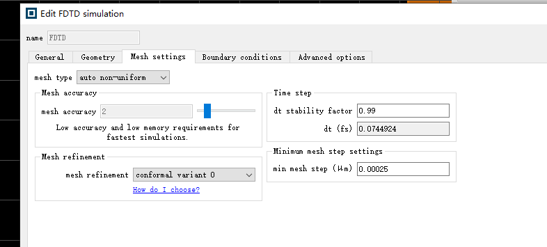
1: Auto non-uniform (default) does not need you to set the mesh. Instead, you choose mesh accuracy as shown in the first figure. Mesh accuracy 2 means 10 mesh cells per min wavelength in material, which is the common, moderate mesh accuracy. You may try mesh accuracy 1, which is poor but in many cases it can lead to meaningful result.
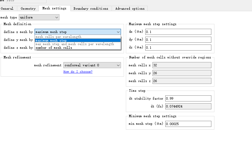
2: Custom non-uniform: it is about the same as the default if you choose "mesh cells per wavelength", except that you can change the mesh grading factor in 3 axes, the same or differently. If you choose other options, it means you know how to set up and why, so it is up to you.
For most cases and most customers, I strongly suggest that you use the default, auto non-uniform mesh. It can be a different story if you know what mesh you need.
-
September 13, 2022 at 1:50 am
2212296
SubscriberFirst of all, thanks for your advice, I feel like I understand a lot. The problem of simulation failure has been discovered by me.
Auto non-uniform: the mesh is determined by the smallest wavelength in material. This means that the refractive index of the material has a great influence.
If the index of refraction of the material is relatively high, say 500, then the minimum wavelength will be smaller than the minimum wavelength emitted by the light source. Therefore, the simulation area is divided into many meshes, which requires more memory to run.
Question: For example, I want to simulate a thin film structure. The refractive index of the film is 500, the thickness is 200nm, the substrate is 1.4, and the thickness is 500um. If I choose 'Auto non-uniform', the minimum wavelength of the grid will be much smaller than the wavelength in the film, resulting in more memory to run.
Solution: Make more meshes in the thin film area and smaller meshes in the substrate area. So, I choose 'Auto non-uniform' + 'mesh', or 'Custom non-uniform' + 'mesh', which one is better?
In addition, if you choose 'Auto non-uniform' + 'mesh', will it still generate more memory, (Auto non-uniform: the mesh is determined by the smallest wavelength in material )
Sincerely.
-
September 13, 2022 at 1:53 am
-
-
September 13, 2022 at 2:20 am
Guilin Sun
Ansys EmployeeI guess you are simulating a metal material? if so, I would suggest to use PEC to replace it, if it is ok.
Please note again that, to get proper simulaiton accuracy, mesh accuracy 2, 10 mesh cells per min wavelength inside the max refractive index (pure dielectric. otherwise you will need to resolve the skin depth) is recommended. you may try mesh accuracy 1, which is 6 mesh cells per min wavelength. Smaller than this is not recommended. If you artificially make the mesh larger using override mesh or other method than the requited mesh density, the simulation accuracy is not guranteed.
-
September 14, 2022 at 12:58 am
2212296
SubscriberReally appreciate your reply. Your work is the most meaningful. However, I still have a few questions.
PEC? (2D materials contain perfect electrical conductors?) How to set it up? Create a 2d material data about conductivity?
Or is there a direct option? I know that refractive index can be calculated from conductivity. I'm going to do a 3d simulation, can I use 2D material data? (PEC)
Are there any examples? ? ?
Sincerely.
-
-
September 14, 2022 at 1:05 am
Guilin Sun
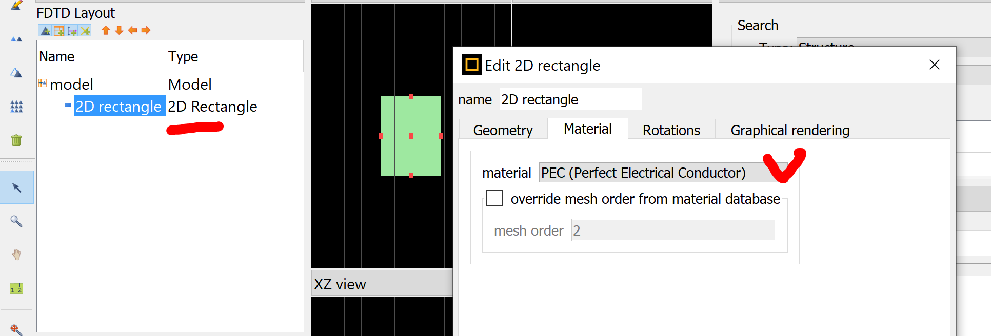
Ansys EmployeePEC (perfect electrical conductors) can be bulk (3D) or 2D sheet. It is in the Material Database:

It has infinite conductivity, so no need to set its material property.
For 2D sheet: https://optics.ansys.com/hc/en-us/articles/360034901593-2D-Rectangle-Simulation-Object
The default 2D sheet material is PEC:

-
September 14, 2022 at 2:24 am
2212296
Subscriberthank you very much
Maybe I didn't express it clearly.
I simulated a 200nm thin film with a real part of 500 and an imaginary part of 400. I still need to set his refractive index property. Will pec help me? ?
-
-
September 14, 2022 at 3:10 am
Guilin Sun
Ansys EmployeeIs the wholde device a thin-film type without small wavelenhth scale structure? if so please use stackrt.
Otherwise FDTD is too heavy to simulate n=500+400i material, even it is 200nm. You can use PEC to simplify it. Please just try first.
-
- The topic ‘About mesh settings’ is closed to new replies.


-
4597
-
1495
-
1386
-
1209
-
1021

© 2025 Copyright ANSYS, Inc. All rights reserved.


