-
-
July 29, 2022 at 5:48 am
zhanggaolu17
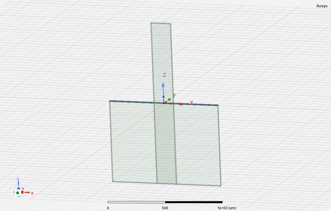
SubscriberHello, I'm a graduate student, not particularly familiar with HFSS, and I've been simulating coplanar waveguide structures recently. The substrate is a 725um silicon substrate. According to the official instruction manual, the size of the wave port is roughly 3 (2*g+w) in width and 4*h-10h in height, so the size of the port is about 300um*3000um, and the aspect ratio is too large. It doesn't feel right. My understanding is that the official reference size is only indicative. For a substrate with a thickness of 725um, the fundamental mode of the coplanar waveguide is completely covered inside, so the overall height of the port should not exceed 2 times the height of the substrate, that is, the bottom of the port should not exceed the bottom of the substrate. The reason why the official guide formula is given is because the boundary of the default wave port is an ideal conductor, but my wave port is touched to the ideal magnetic boundary, so the edge of the wave port is a natural boundary condition, so there is no need to refer to the guide formula, it should be set according to the actual device size The size of the port, the only difference is whether it will contain more modes. In fact, the larger the port, the more convergent the propagation constant and effective refractive index of the fundamental mode of the coplanar waveguide. Am I right? Thanks!
-
July 29, 2022 at 5:50 am
-
August 3, 2022 at 7:25 am
Chinmay T
Forum ModeratorHi @zhanggaolu17,
What are you referring to as official instruction manual?Please refer to the inbuilt co-planar waveguide and co-planar waveguide with ground examples for better understanding.Thanks,
Chinmay
-
- The topic ‘gamma changes as the waveport size changes’ is closed to new replies.


- Y wiring method and the start and end points of winding.
- Lumped Port Deembed
- Hfss 3D pcb via capped and filled with epoxy
- Optimizing Via Impedance in Ansys HFSS 3D Layout Using Geometric Parameter Sweep
- AEDT Natural Convection with default correlation is failing solver initializatio
- HFSS libnvidia-ml.so too old or could not be found – Warning in slurm job output
- Three-Phase Voltage Imbalances in dual stator electric generator
- STL Import Errors in HFSS After Cleaning in SpaceClaim
- Calc Error in Field Calculator after PyAEDT Analyze
- import file autocad 3d

-
3862
-
1414
-
1220
-
1118
-
1015

© 2025 Copyright ANSYS, Inc. All rights reserved.


