-
-
July 14, 2022 at 8:57 pm
emily.frede
SubscriberHello, Learning Forum!
I am working on a research project in which I've been investigating light transmission, especially light in guided modes, through different micron-scale structures. I've been using Lumerical's FDTD software to build the models and run simulations, and I've run into some unexpected mode results that I've described in detail below. If I should be posting this question somewhere else, or contacting customer support directly, please let me know!
--
I have changed a cylindrically-symmetric model to include radial birefringence in one of the materials, and now when I calculate the modes I am observing odd asymmetric behavior. I am wondering what could have caused this (my model is still symmetric as far as I can tell) and if there's anything I can do in the software to see symmetric modes for this model -- or if it is some intrinsic asymmetry (which I think is unlikely).
Â
My basic structure is a single solid cylinder being enclosed by a hollow cylinder (outer radii 0.6 microns and 1 micron respectively). The outer layer (the hollow cylinder) has a higher refractive index than the inner cylinder, and I am investigating how light is guided through this structure.
In previous simulations, I specified these structures to have constant refractive index (outer layer 1.44, inner layer 1.38, environment 1.00), and found that the modes reflected this symmetry -- see especially mode 3 and mode 6 in the picture below.
Now, I am specifying the outer structure to have positive birefringence along radial optic axes. I have followed the steps to encode an anisotropic material ( https://optics.ansys.com/hc/en-us/articles/360034394694-Creating-anisotropic-optical-materials-in-FDTD-and-MODE ) in the software.Â
The diagonalized permittivity matrix (being in cylindrical coordinates) looks like the matrix below. Note n_{e} is the refractive index for light travelling radially, n_{o} is the refractive index for light travelling in the phi or z directions.Â
epsilon = [ n_{e}^2, 0, 0; 0, n_{o}^2, 0; 0, 0, n_{o}^2 ]
Since this anisotropic material is diagonal in cylindrical coordinates, I have encoded this in the material using the material database (which uses Cartesian coordinates, but I later convert this to cylindrical coordinates). Diagonal anisotropy can be specified in a material by specifying n_{x}, n_{y}, n_{z} as seen in the form n = [n_{x}, 0, 0; 0, n_{y}, 0; 0, 0, n_{z} ]. I have included a screenshot of this as well. I am currently using the values: n_{x} = 1.8 (which specifies this for the radial direction), n_{y} = 1.4 (phi direction), and n_{z} = 1.4 (z direction). The settings I have input, and the index monitor profiles, are shown in the picture below. Again, everything looks like it should here.
Since I am using a cylindrical coordinate system here, I have made use of the matrix transform grid attribute ( https://optics.ansys.com/hc/en-us/articles/360034915173-Matrix-Transformation-Simulation-object ) in the software. This essentially specifies new unit vectors in a given area of the structure. I have generated cylindrical unit vectors at each point in the hollow cylinder material (which is centered around the origin and has well-known inner and outer radii).Â
I have set up a grid of 801 by 801 points, to span the two-dimensional area which is 4 microns along both x and y axes (the cross-section is a square). For points outside the outer radius of the hollow cylinder (the background environment) and for points inside the inner radius of the hollow cylinder (the solid cylinder in the center), I specify the identity matrix as the matrix transform U since there is no coordinate transformation needed here. For points within the outer and inner boundaries of the hollow cylinder, I implement a cylindrical coordinate matrix transformation. I want the software to use the refractive index information for the x direction (n_{x}) as the refractive index for the radial direction; similarly to use n_{y} for the \phi direction and n_{z} for the z direction (this last one is unchanged). So the matrix U (that ensures a permittivity matrix \epsilon is diagonal as seen on this page: https://optics.ansys.com/hc/en-us/articles/360034394694-Creating-anisotropic-optical-materials-in-FDTD-and-MODE ) at a given point (x, y, z) is:
U = [ cos(phi), - sin(phi), 0; sin(phi), cos(phi), 0; Â 0, 0, 1 ] where phi = atan2(y, x)
So I have calculated (in MATLAB) a U matrix at each point in the 801 by 801 grid I have set up (which, for points within the hollow cylinder cross-sectional area, implements a cylindrical coordinate transformation). (Since position on the z-axis doesn't affect the matrix transform whatsoever, I duplicate this data so it can be applied at an 801x801 grid at z = 0 microns and an 801x801 grid at z = 4 microns and the software knows it is constant with respect to z.)Â
I am confident that this is working as I intended it to, according to the visual aids of the matrix transformation grid attribute that, when the grid attribute is added to the model, indicate the specified unit vectors. On the image below, you can see that within the light yellow area (the hollow cylinder) each blue arrow (usually indicating the x-direction) points radially outward and each green arrow (usually indicating the y-direction) points in the phi direction. (I have changed the colors of the structures so these matrix transformation arrows are more visible.)
So to my knowledge, everything about the model is working properly and there is well-established cylindrical symmetry about the structure (which I've placed on the origin). However, when I calculate the modes for this new model (with the radial birefringence included), I am finding breaking of symmetry that I did not find in the old model. There seem to be modes that arbitrarily choose spots within the high-refractive-index hollow cylinder to have higher intensity than others. Some extreme examples include a single smeared spot of high intensity on one side of the hollow cylinder, with low intensity on the other side. I have not been able to find a mode like mode 3 or mode 6 in the mode picture above. Examples of the modes I am finding with this new model are shown in the picture below.
So, might there be anything in the software that is causing this? Have I done something wrong in implementing my model into the software? Does anyone have any ideas as to why the modes are non-symmetric when I am implementing the radial birefringence? Many thanks in advance!
-
July 15, 2022 at 4:52 pm
Guilin Sun
Ansys EmployeeThank you for the detailed description!
It could be due to 2 reasons:
1: the anisotropy attributes may not function as expected;
2: the mode degeneracy makes the results look like ackward.
Suggested solutions:
1: I would recommend to numerically calculate the refractive index in xy coordinate, and import the index, which will be simpler: https://optics.ansys.com/hc/en-us/articles/360034901993-Spatial-n-k-data-Simulation-object2: use symmetry BCs to isolate the modes: https://optics.ansys.com/hc/en-us/articles/360034382694-Symmetric-and-anti-symmetric-BCs-in-FDTD-and-MODE
-
July 29, 2022 at 4:00 pm
emily.frede
SubscriberThank you for your response! I have been examining your suggestions and comparing the refractive index monitor results with expectations, I've included this in my reply below (my apologies, I didn't realize that I should reply directly to your comment here!).
-
-
July 29, 2022 at 4:36 am
emily.frede
SubscriberThank you for your response! I have been working on this in the meantime, considering both your suggestions and re-examining the index monitor results (I'll explain below).
First, I can see the use of encoding a custom material by it's refractive index, but in this situation it is possible and more efficient to code it directly.Â
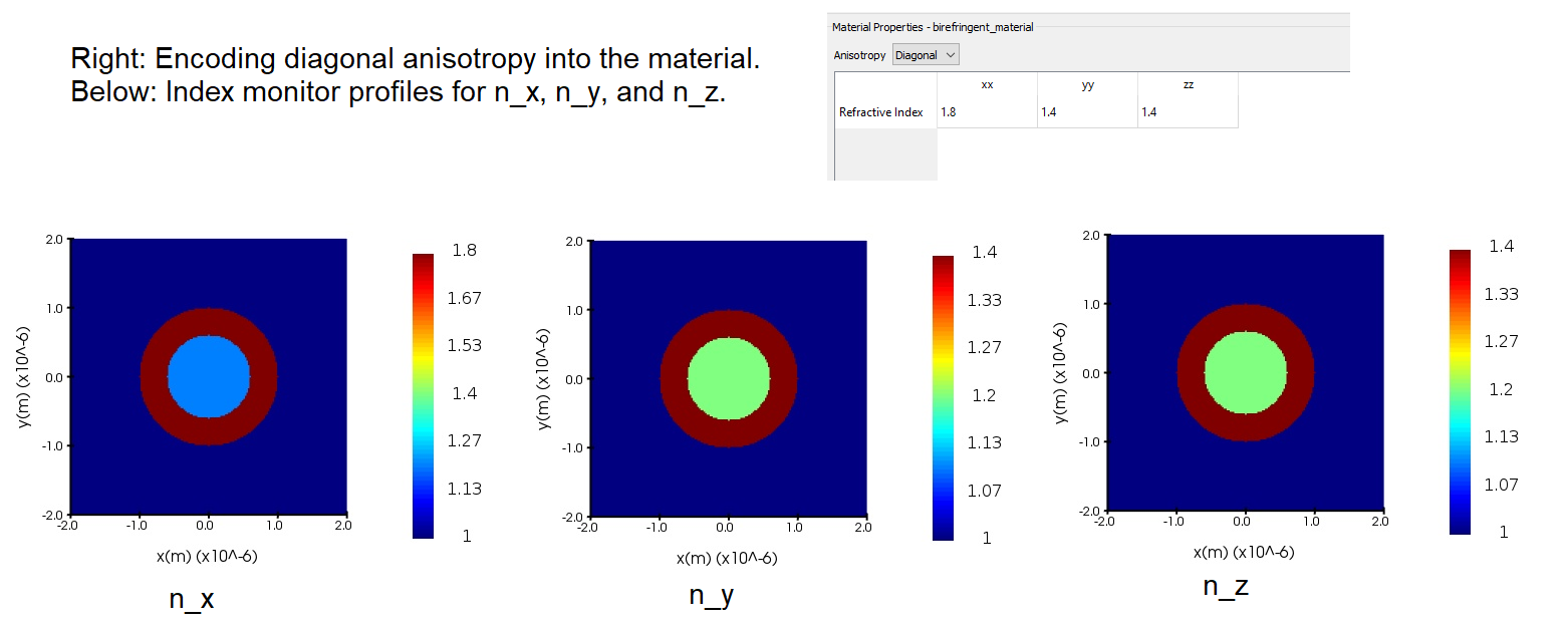
When specifying custom material by its refractive index, the refractive index matrix must first be diagonalized so that at each point (x,y,z) only [n_{xx}, n_{yy}, n_{zz}] are specified (all off-diagonal elements are zero). My refractive index matrix is already diagonalized as seen in cylindrical coordinates, as it is:Â
n = [ n_{e}, 0, 0; 0, n_{o}, 0; 0, 0, n_{o} ] where n_{e} = 1.8 and n_{o} = 1.4
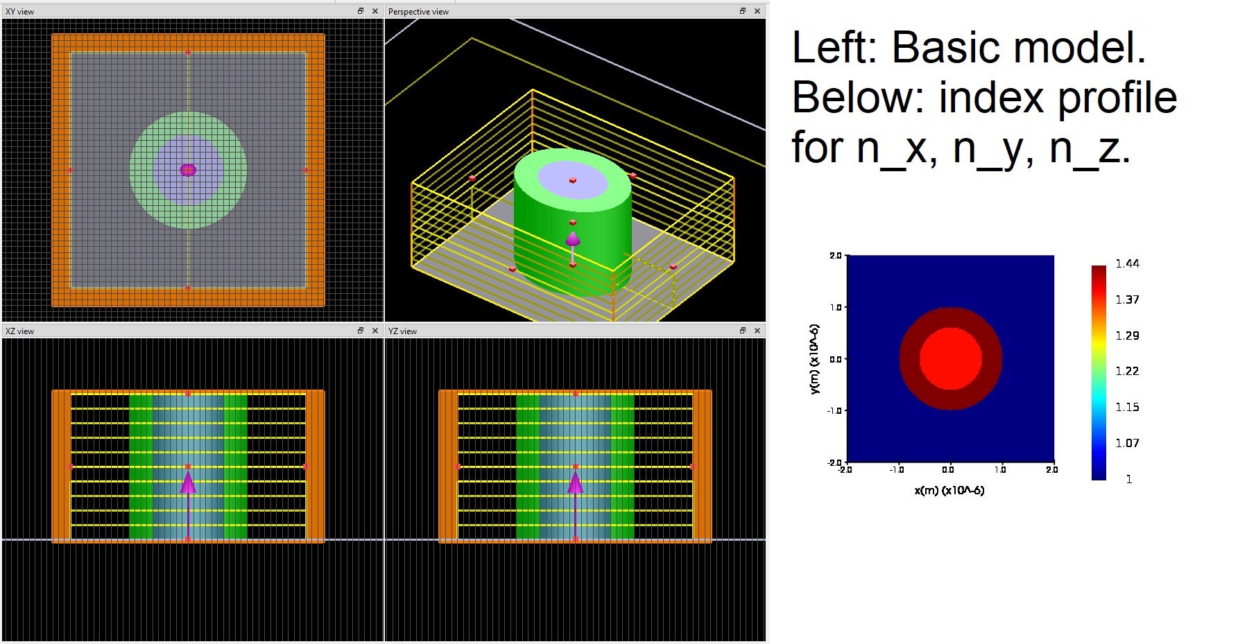
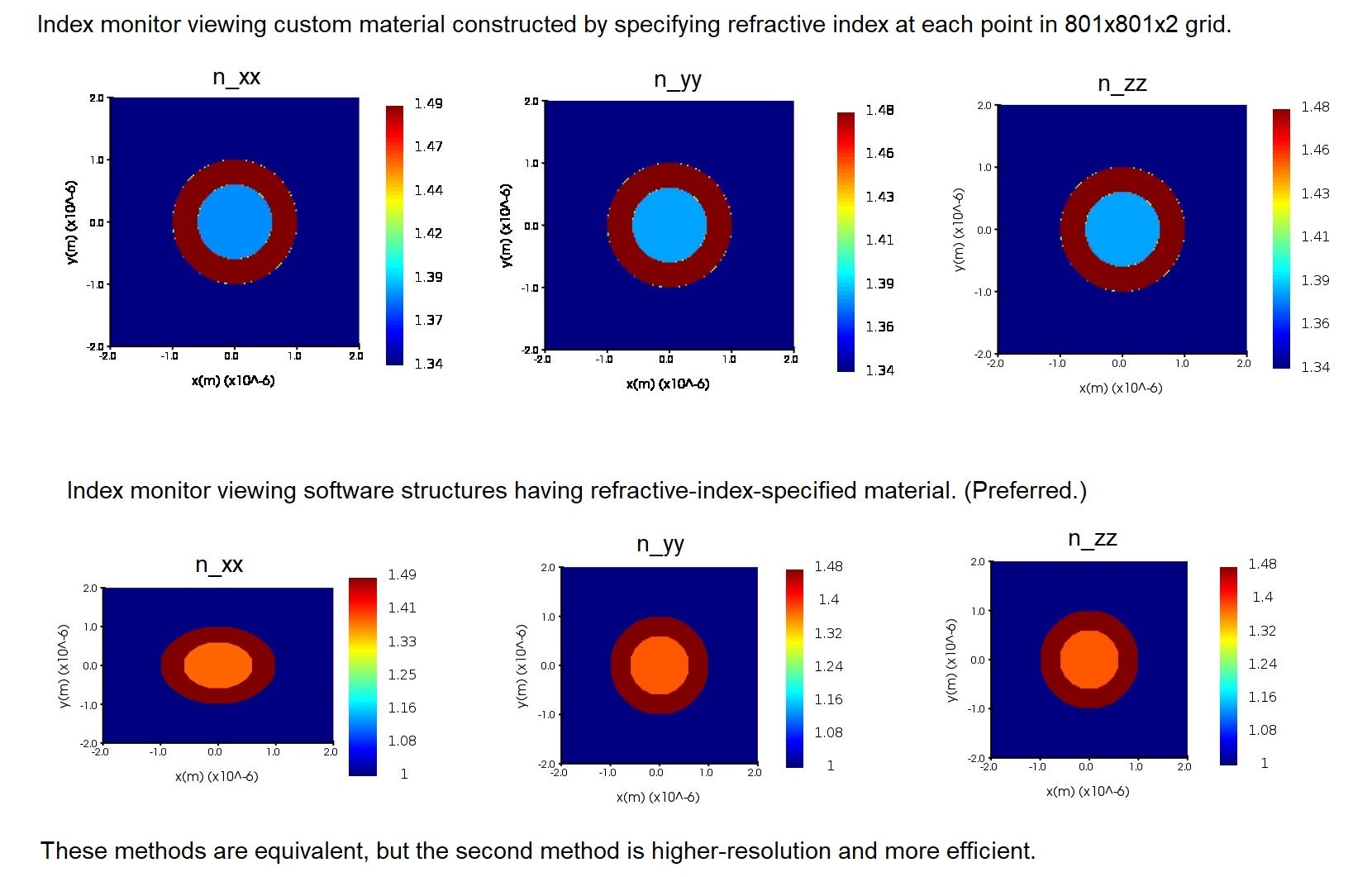
I have explored this method, and it gives the same results as specifying the anisotropy directly. When I state the refractive index at each point (x,y,z) in an 801x801x2 grid, the index monitor shows the same material properties as if I specify the refractive indices by material for the given structures -- though the latter is more exact and doesn't cause any points of intermeadiate refractive index along the borders of the structures, as in numerical calculation. (Note here that the environment is set to 1.34, the inner cylinder is set to 1.38, the outer layer radial direction is set to n_{e} = 1.49 and the outer layer phi and z directions is set to n_{0} = 1.48.)
Next, I appreciate your mentioning symmetry boundary conditions. I am concerned that this doesn't solve underlying asymmetry for the full-scale simulation. Symmetric boundary conditions are used for making the simulations more efficient but doesn't change any underlying behavior (when applied correctly). If I, for instance, only simulate the top-right quarter of the cross-section of the structure, and correctly apply boundary conditions, it should be the same as running the simulation with the whole cross-section. So the underlying asymmetry in these full simulations remains unexplained.
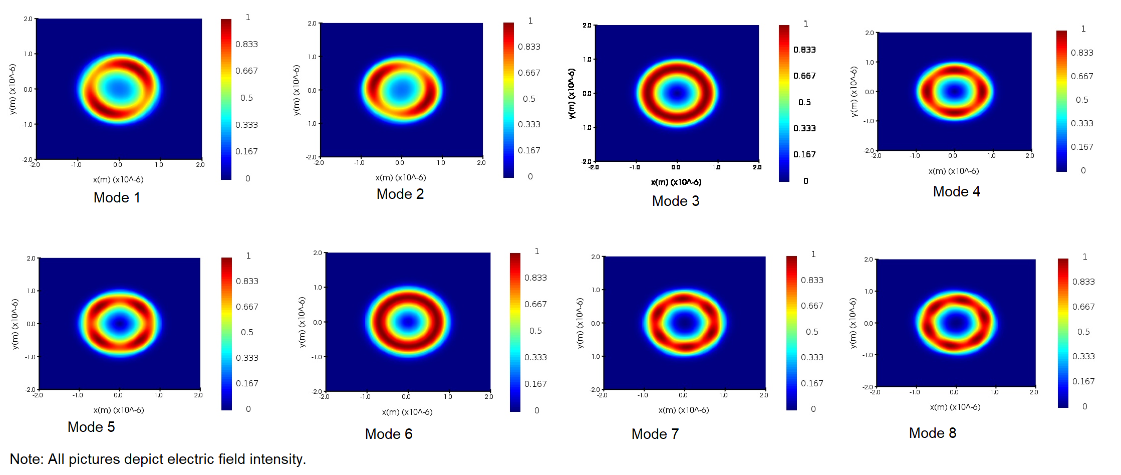
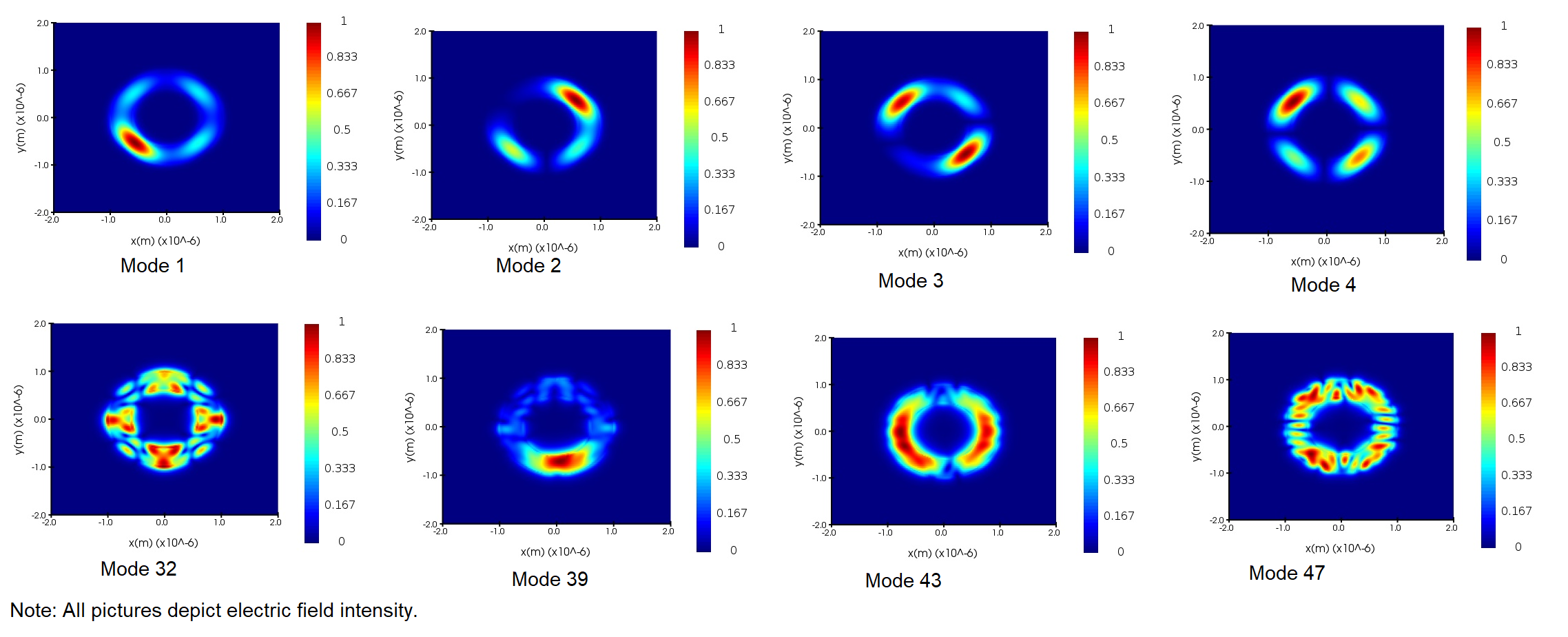
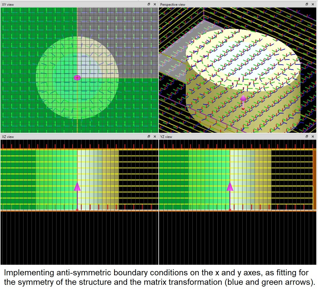
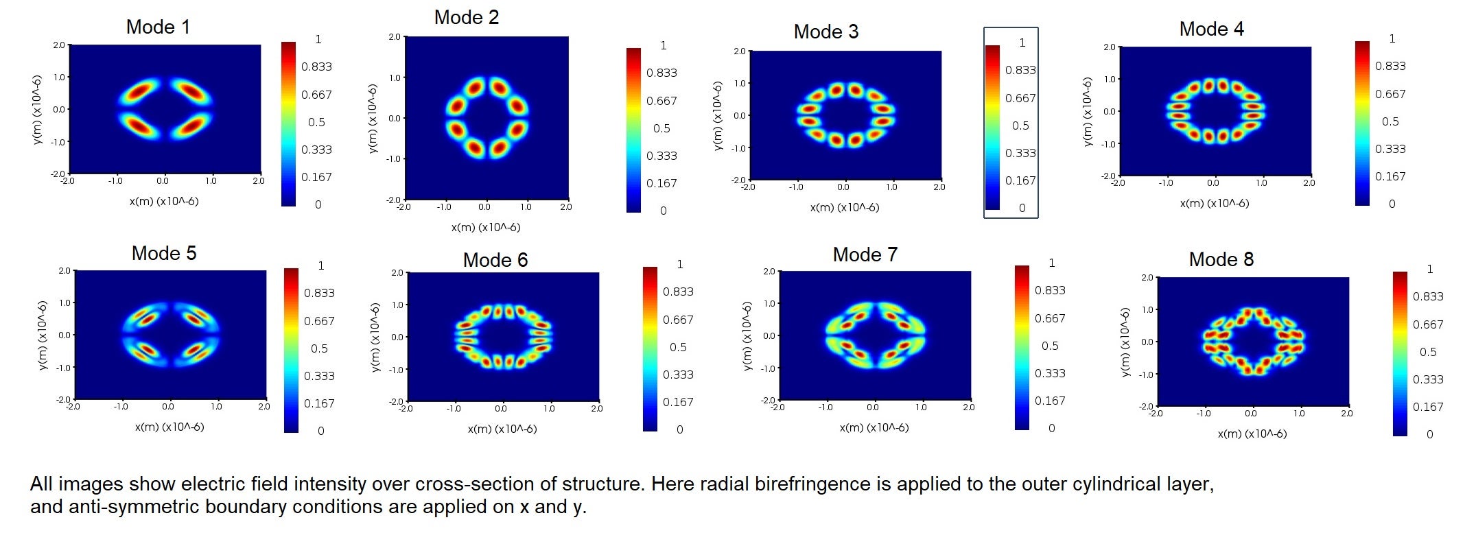
Due to the symmetry of the structure (including of the matrix transform, which is specifying radial and phi directions), anti-symmetric boundary conditions on the x and y axes should be appropriate. I am finding modes that have balanced intensity over the x and y axes, as shown in the image below (these show electric field intensities, the following behavior is also correspondingly very evident in the electric field vector plots of the modes). The position of the nodes seem to be affected by these boundary conditions -- again this is in a symmetric way, but I'm not confident that this describes the true behavior of the full cross-section (my point in the previous paragraph). These have resulted in rather "squarish" or "boxy" modes as opposed to smooth/round modes. My expectation (based off my prior simulations without the radial birefringence, as seen in the modes in the second picture in my original question) would be that the nodes and intensities are distributed more evenly, even to the point of forming a ring in the outer layer with uniform intensity.
You mention that mode degeneracy may be playing a role in the asymmetry. Can you expand on this a bit more? I have encountered the concept of mode degeneracy as being light of the same frequency comprising differing patterns -- usually related by some linear transformation (rotations and reflections)? -- but I don't see how this would affect the symmetry at all.
Lastly, I want to bring up another avneue of my investigation into this problem, and inquire if the software is performing calculations how I am expecting.Â
When I use the index monitor to view [n_{xx}, n_{yy}, n_{zz}] of the entire structure, I am finding constant values as shown in the picture below -- this is the index monitor image that I find with the software currently. On Lumerical's website (the link https://optics.ansys.com/hc/en-us/articles/360034915193-Tips-and-background-information-when-using-grid-attributes under section "Index monitor currently record only diagonal index") it mentions that the index monitor can only show these diagonal elements of the refractive index matrix, so encoding the anisotropy must be done carefully -- I would presume because the non-diagonal elements may not be zero. So I cannot view an element such as n_{xy} in the index monitor.
However, since I have the transform matrix between coordinate systems (the Jacobian J) and I know all the refractive indices, I can view the entire refractive index matrix in Cartesian coordinates by plotting this in MATLAB. I have included my calculation and the MATLAB plots for each matrix element below. Note here n_{rr} = 4, n_{phiphi} = 3, and n_{zz} = 2 were chosen to fully illustrate the behavior.Â
n_{Cartesian} = J^{-1} n_{cylindrical} JÂ
n_{Cartesian} = [ cos(phi), sin(phi), 0; - sin(phi), cos(phi), 0; 0, 0, 1] [ n_{rr}, 0, 0; 0, n_{phiphi}, 0; 0, 0, n_{zz} ] [ cos(phi), - sin(phi), 0; sin(phi), cos(phi), 0; 0, 0, 1]Â
n_{Cartesian} = [ n_{rr} cos^2(phi) + n_{phiphi} sin^2(phi), ( n_{phiphi} - n_{rr}) cos(phi) sin(phi), 0; (n_{phiphi} - n_{rr}) cos(phi) sin(phi), n_{rr} sin^2(phi) + n_{phiphi} cos^2(phi), 0; 0, 0, n_{zz} ]
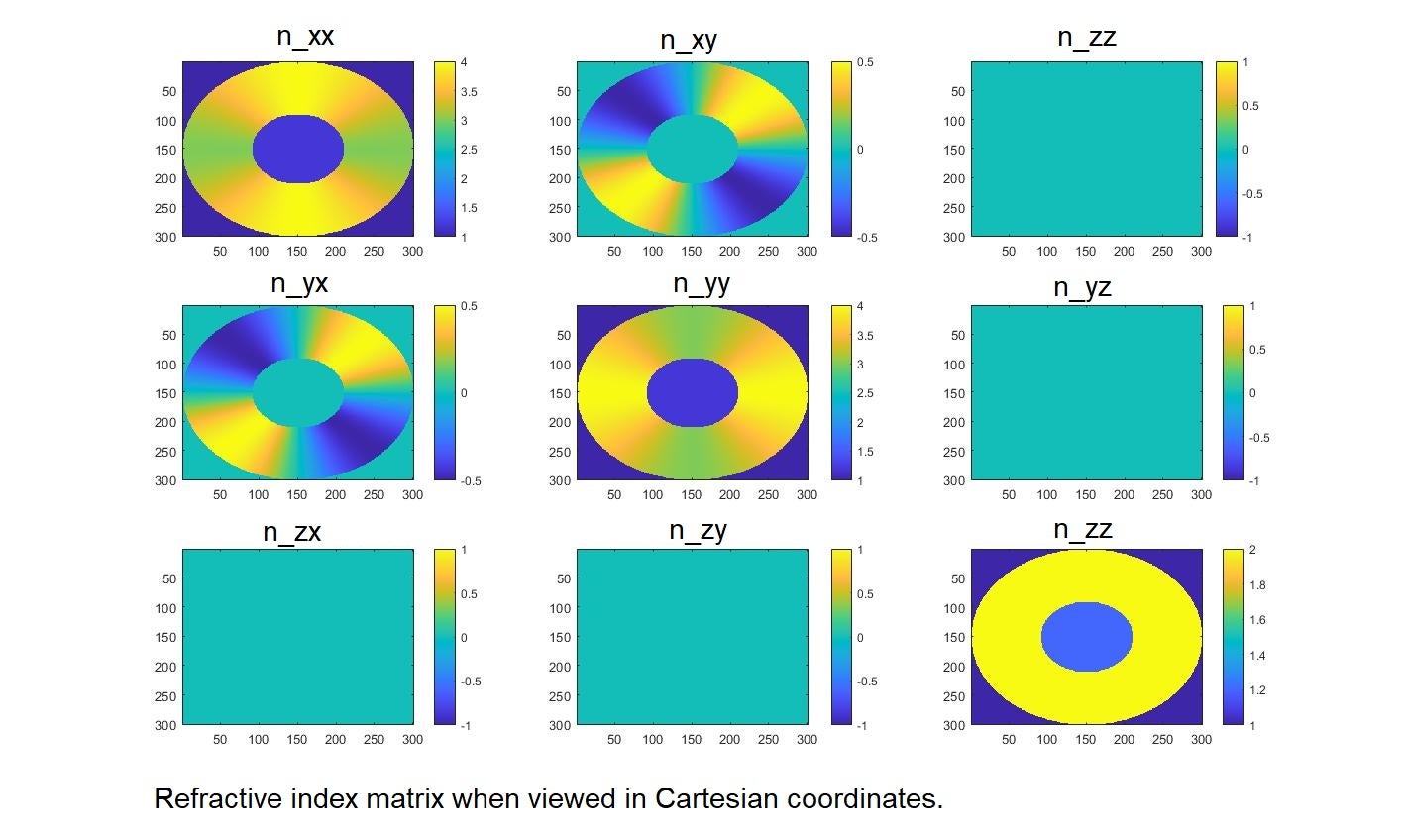
Even when restricting our view in my MATLAB plots to the diagonal elements n_{xx} and n_{yy}, there is clearly a gradient in the refractive index as observed in the xy plane.Â
If the matrix transformation is applied before the index monitor views the refractive index, then I should be seeing a gradient in the Lumerical index monitor as seen in these MATLAB plots. If the matrix transformation is applied after the index monitor views the refractive index, then I was correct in assuming that my current index monitor pictures are correct. Since the website notes that "index monitors do not record any information about the permittivity transformations" ( https://optics.ansys.com/hc/en-us/articles/360034915193-Tips-and-background-information-when-using-grid-attributes ) I assumed it was the latter, but I am reconsidering this and would appreciate clarification!
If my index monitor plots are correct, I am still unsure what the cause of the asymmetry is. If my index monitor plots are incorrect, there is clearly a problem encoding the anisotropy, and any guidance on how to fix this would be most appreciated!
Thank you again for your input, and I am open to further ideas from anyone!
-
August 13, 2022 at 6:01 pm
emily.frede
SubscriberThank you for the input I've received, and I am happy for any further advice or insight on this post about the mode asymmetry! I am now narrowing my focus to consider the results of the index monitor in comparison with the expectation plots I've generated in MATLAB, which I have just posted now at this link:
/forum/forums/topic/what-does-an-index-monitor-show-when-a-matrix-transform-is-being-used/
-
- The topic ‘Incorporating radial birefringence breaking cylindrical symmetry of the modes?’ is closed to new replies.
-
6379
-
1906
-
1457
-
1308
-
1022
© 2026 Copyright ANSYS, Inc. All rights reserved.


