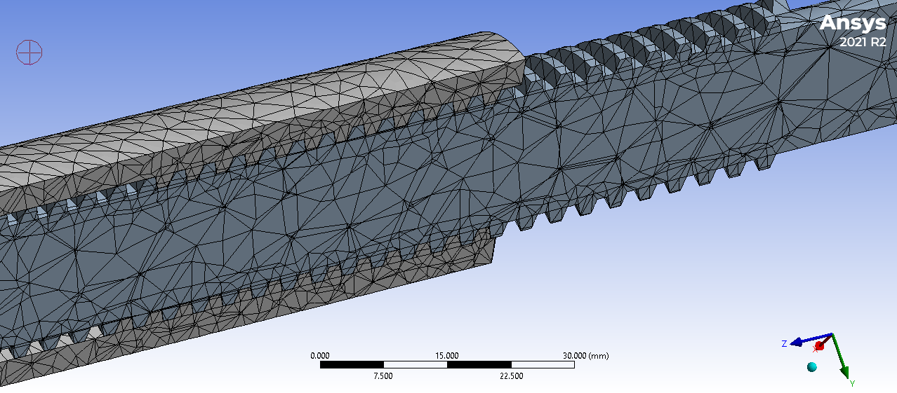
Hi, i am working on a very simple design of power screw (Lead screw with tripozoidal threads) having threaded Bolt rod and partial Threaded Nut Rod. In Mechanical Model, The Frictional Contact was made between threaded Surfaces. Cylindrical Joint was made (Body to Body) so that Nut side Rod Rotates and Translates. The Meshing elemnet size was 3mm as shown in picture.
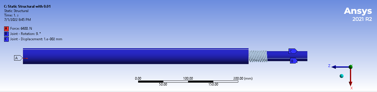
In Static Structure analysis, The Force of ramped 6400N was applied on Nut Rod end surface. Bolt Rod side was fixed with fixed support and joint load with rotation of 9 degree ramped was applied on Nut Rod. and also Joint load with displacement of ramped 0.01mm was applied on NUT SIDE, (i selected those values with little variation with actual thread pitch which was 4mm per rotation. Those Two values on joint can be an issue as if i apply them according to the nut bolt pitch, the stresses on threads dont appeare, may be due to No contact between surfaces, so i have to varry them to make contact) (kindly give me a better solution for this issue).
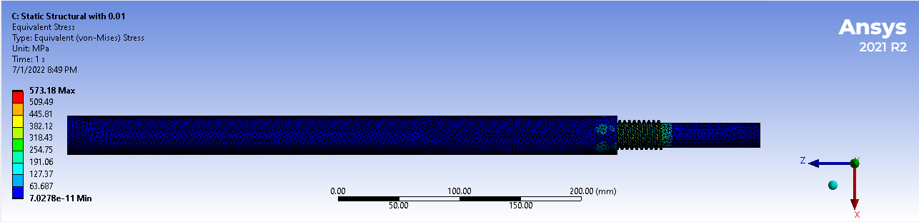
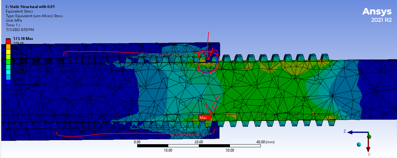
With large diflections ON, and analytical setting of initial time step of 0.05 and max step of 0.2. The solution took too much time. The stresses on threads are not symmetric. First thread surfaces of Nut bolts are having large stresses on bolt one first thread making the stresses to go on plastic regime (which would not actually be like this, if all threads carry equal stresses) as shown in Figure.
Kindly suggest me to overcome this issue. More, the stresses highly depend on the Joint Loads (Rotational and Displacement) and solution doesnt converge if i varry them too much or change the direction agaisnt the pitch thread. (More, this solution is independent of applied Force as i changed the force to 1000N but got same stresses). (One More thing, if i bring this set up in Transient structural, the solution goes till step equal to 1 and then become non-converged, means there is an issue in applying conditions). & The file is not attaching due to some issue.


