Blog Posts infinite loop
Hello everybody.
I have a 2D mesh in Ansys meshing which takes 5 minutes to mesh 101K cells over 0.3 m, it takes 15 for 140 K over 0.5m (see its mesh as ttached finished mesh) and more than 24 hourse for 0.6 m (if finish).
I have a 2D channel with length of 2.6 m, and mean height of 0.13 m. The bottom bed is following a dune (curvy) shape which small semicircles are over the bed. The small secmicircles have length (diameter) of 0.003 m (=3 mm) and height (radius) of 0.0015 m (=1.5 mm) , and the gap between these semicorcles is 0.0002 m (=0.2 mm). so there is almost 350 semicircles at each meter, and 820 in total.My target mesh is y+ close to 1 at the bottom boundary (which is a wall explained above), and this needs first cell height of 3-e5.
Before explaining the mesh criteria below, I have to mention that top boundary is symmetry and two sides should be suitable for conformal periodicity, so sides should have the same mesh.
Now mesh criteria I am using are as follows:
- deviding the domain to 2 bodies under a single part to have faster strutured mesh at top (most of the domain) and have faster mesh there, while keeping bottom quad dominant.
- main mesh settings for whole domain are: element size = 3e-3, adaptive sizing = No, Growth rate = 1.1, defeaturing = No, capture curvature = Yes, Curvature min size = 1e-4, curavture normal angle = 20 deg, capture proximity = No, smoothing = medium, number of CPUs for parallel part meshing = 18, sheet body method = Quad dominant
- I have "method" for both bodies as : method = Multizone Quad/Tri, Surface Mesh method = Pave, Free face mesh type = All Quad, Preserve boundaries = Protected
- sizing over bottom wall (the semicircles over the dunes) as : 546 edges for 0.6 m length (2 arcs for each semicircle and 1 straight line for each gap), elemnt size = 3e-5, other settings as default controlled by main main mesh settings mentioned above.
- sizing over two sides of bottom body to have the same mesh for periodicity as : element size = 5e-4, Bias = Smaller close to the borrom, Bias factor = 50, other settings as default controlled by main main mesh settings mentioned above.
- sizing over two sides of top body to have the same mesh for periodicity as : number of elements = 20, Bias = larger at middle and smaller at top and borrom, Bias factor = 2, other settings as default controlled by main main mesh settings mentioned above.
As mentioned at the beginning, the meshing for small length of channel with the same setting and almost the same height (the bottom wall is curvy) is fast, but in increases from 1 min for 38 k for 0.1 m to 30 minutes for just 190 K for 0.5 m. When the domain is 0.6 m and everything is as before, it takes more than 1 day and still nothing.
Some additive informations are that:
- I am using Ansys meshing v261.
- All quad method instead of multizone increases the time.
- Increasing bottom sizing from 3e-5 to 5e-4 gives the mesh after 12 hours, but still the time is too much for such a mesh, and very coarser than what I need.
- Uniform instead of pave is not desired close to semicircles as mesh destribution is not good as Pave. Growth rate of bottom body controls the mesh sizing along channel in top body as if growth is large, the cells which are at connection of two body are larger so size along channel at top body is larger.
- Using inflation layer over bottom wall is possible, but only whit a few layers because increasing layers leads to very slweed of cells in the gap are close to the wall when semicircles connect to bed. even some numer of layers crash.
- Usning match control gives error and is not applicable
- I understand that y+ of 1 may not be reasonable, but beside that, I need high reolution at the bottom close to semicircles, so cell sizing around 3e-5 and growth rate less than 1.1 is the only way I know for this problem.
- It maybe related that sometimes CPU has burst of usages during mesh (see the attached) and not caped at a performance, which I think comes from communication among cores. However I think the problem is not CPU or ram and it comes from my setting.
At the end, this is a very important simulation for me and I have been trying different things, but no solution. I appreciate your help in this manner, and please let me know for further indformation.
[topic_link] => https://innovationspace.ansys.com/forum/forums/topic/too-long-2d-mesh-generation/ [topic_status] => publish [topic_published_date] => August 5, 2026 [author] => 10902681@polimi.it [like_count] => 0 [reply_count] => 1 [view_count] => 21 ) [2] => Array ( [topic_id] => 461841 [topic_title] => Conflict between marginal ray and first-order gives the wrong focal length [topic_content] =>Hi everyone!
I'm a beginner at Zemax. I'm simulating the eye, using Marginal ray height to solve the thickness of surface 4. However, whenever I click on FIRST order in the Macro list to find the focal length, the value at the LDE turns out to be 0.
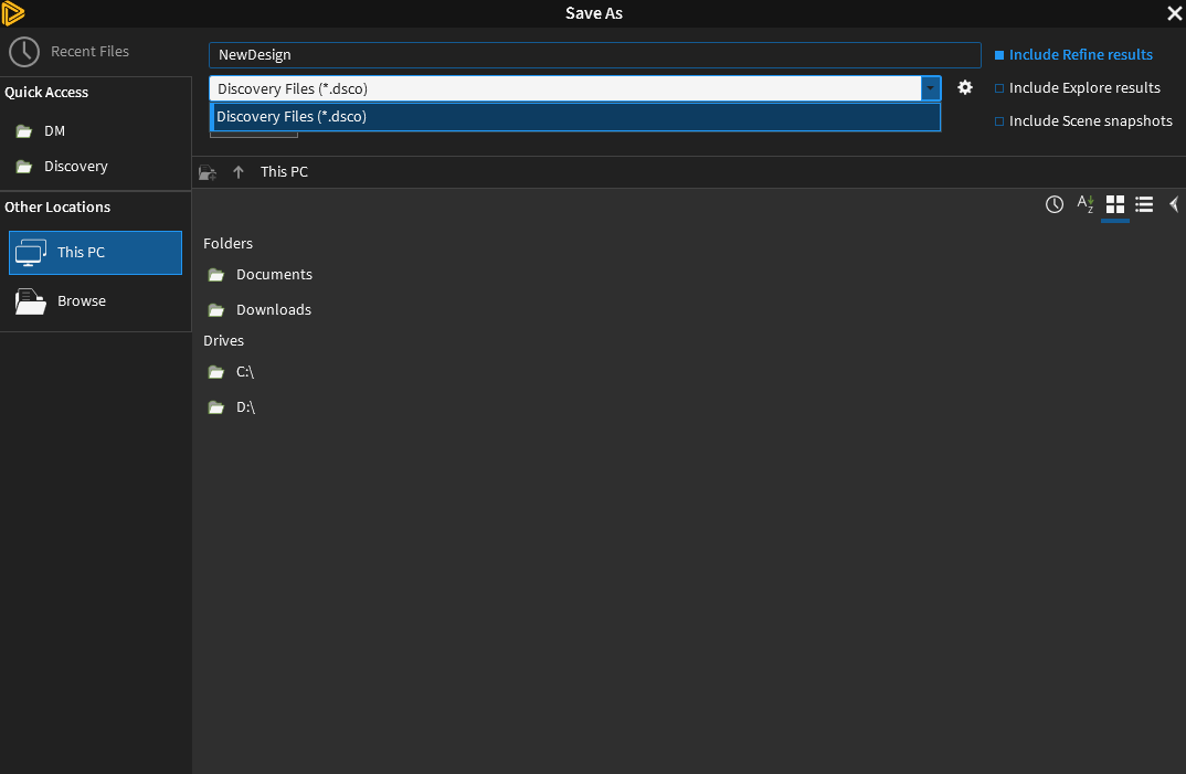 </p><p>I am trying to save a model as a file format compatible with LS-Dyna, however when I open the dropdown menu in Save As, I only see .dsco as a file save option. Please let me know if I am missing anything.</p>
[topic_link] => https://innovationspace.ansys.com/forum/forums/topic/saving-discovery-2026-r1-geometry-as-different-file-formats/
[topic_status] => publish
[topic_published_date] => July 22, 2026
[author] => 00075926@richland2.org
[like_count] => 0
[reply_count] => 1
[view_count] => 102
)
[5] => Array
(
[topic_id] => 461544
[topic_title] => PyDiscovery Release Clarification
[topic_content] => <p class="PDq2pG_selectionAnchorContainer" data-start="43" data-end="57"><strong data-start="43" data-end="57">Hi ,</p><p data-start="92" data-end="192">May I know if there is any tentative Ansys release in which PyDiscovery is expected to be available?</p><p data-start="197" data-end="225"><strong data-start="197" data-end="209">Regards,<br data-start="209" data-end="212">Bhargav Ram</p>
[topic_link] => https://innovationspace.ansys.com/forum/forums/topic/pydiscovery-release-clarification/
[topic_status] => publish
[topic_published_date] => July 21, 2026
[author] => Bhargav.Bobbili-Int@cadfem.ai
[like_count] => 0
[reply_count] => 0
[view_count] => 111
)
[6] => Array
(
[topic_id] => 461482
[topic_title] => How to create a regular wave on an ellipse in ANSYS DesignModeler
[topic_content] => <p class="isSelectedEnd">Hello,</p><p class="isSelectedEnd">I am working on a 2D simulation in ANSYS DesignModeler.</p><p class="isSelectedEnd">I have a question: how can I create a regular wave pattern along the entire ellipse, and only on a selected part of it, as shown in the attached pictures?</p><p class="isSelectedEnd">Thank you in advance for your help!</p><p>Best regards,<br>
</p><p>I am trying to save a model as a file format compatible with LS-Dyna, however when I open the dropdown menu in Save As, I only see .dsco as a file save option. Please let me know if I am missing anything.</p>
[topic_link] => https://innovationspace.ansys.com/forum/forums/topic/saving-discovery-2026-r1-geometry-as-different-file-formats/
[topic_status] => publish
[topic_published_date] => July 22, 2026
[author] => 00075926@richland2.org
[like_count] => 0
[reply_count] => 1
[view_count] => 102
)
[5] => Array
(
[topic_id] => 461544
[topic_title] => PyDiscovery Release Clarification
[topic_content] => <p class="PDq2pG_selectionAnchorContainer" data-start="43" data-end="57"><strong data-start="43" data-end="57">Hi ,</p><p data-start="92" data-end="192">May I know if there is any tentative Ansys release in which PyDiscovery is expected to be available?</p><p data-start="197" data-end="225"><strong data-start="197" data-end="209">Regards,<br data-start="209" data-end="212">Bhargav Ram</p>
[topic_link] => https://innovationspace.ansys.com/forum/forums/topic/pydiscovery-release-clarification/
[topic_status] => publish
[topic_published_date] => July 21, 2026
[author] => Bhargav.Bobbili-Int@cadfem.ai
[like_count] => 0
[reply_count] => 0
[view_count] => 111
)
[6] => Array
(
[topic_id] => 461482
[topic_title] => How to create a regular wave on an ellipse in ANSYS DesignModeler
[topic_content] => <p class="isSelectedEnd">Hello,</p><p class="isSelectedEnd">I am working on a 2D simulation in ANSYS DesignModeler.</p><p class="isSelectedEnd">I have a question: how can I create a regular wave pattern along the entire ellipse, and only on a selected part of it, as shown in the attached pictures?</p><p class="isSelectedEnd">Thank you in advance for your help!</p><p>Best regards,<br>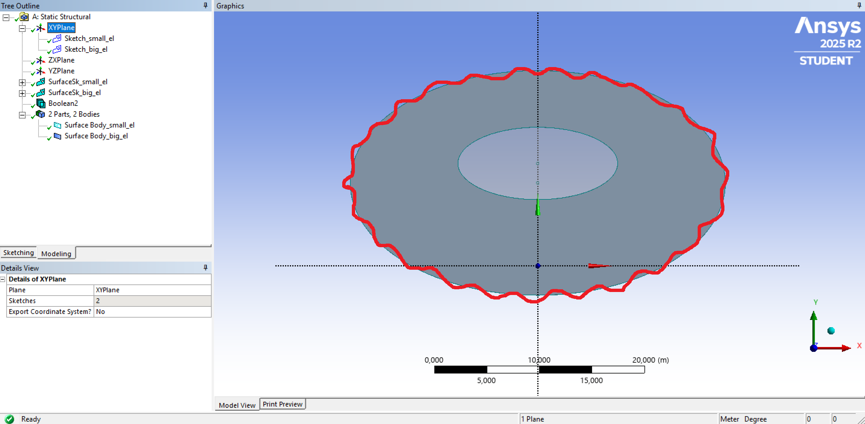 <br><br>
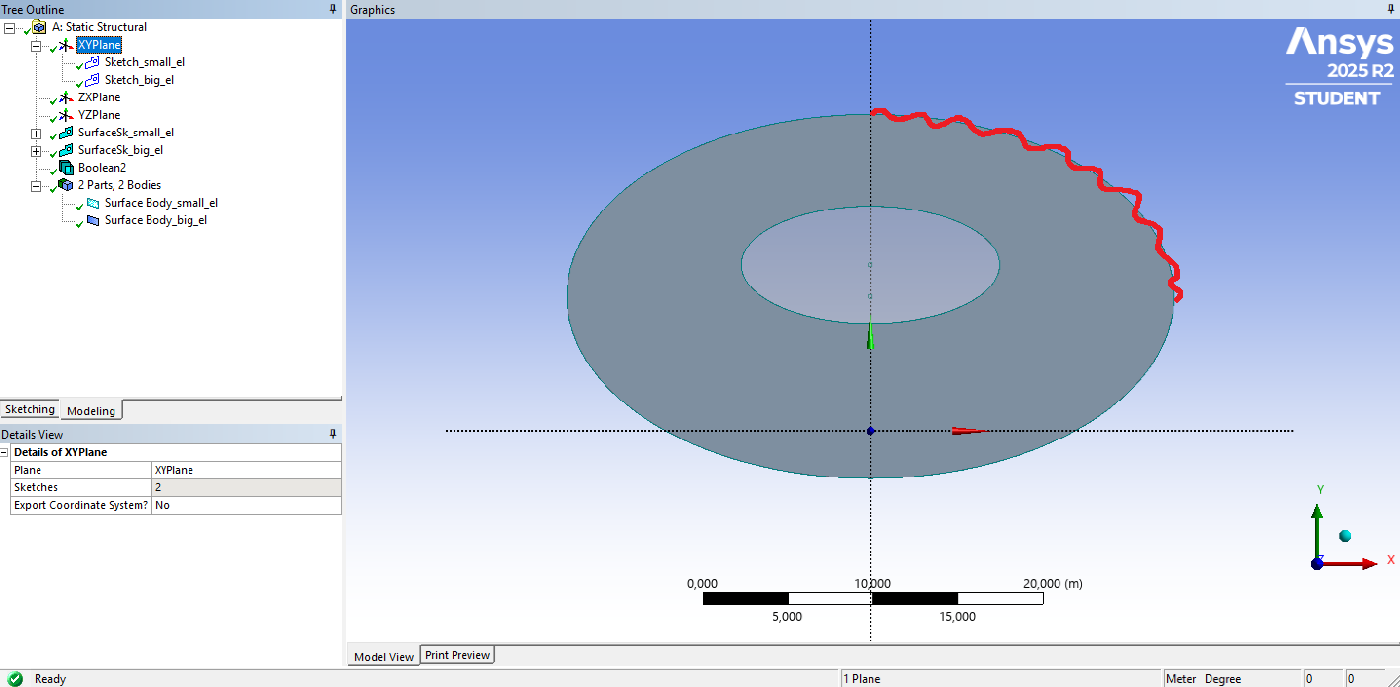 </p>
[topic_link] => https://innovationspace.ansys.com/forum/forums/topic/how-to-create-a-regular-wave-on-an-ellipse-in-ansys-designmodeler/
[topic_status] => publish
[topic_published_date] => July 19, 2026
[author] => flying3tiger3@gmail.com
[like_count] => 0
[reply_count] => 0
[view_count] => 125
)
[7] => Array
(
[topic_id] => 461398
[topic_title] => messy font size display in SpaceClaim
[topic_content] => <p><p>Hi all,</p><p>I've currently downloaded Ansys 22R2 in a new laptop (win11). It is the first time to download Ansys in the laptop. However, it's found that the interface display size ratio is totally in a mess, which lead to a terrible modeling experience. The problem is marked in the following pictures. As you can see, in the structure tree, the box is smaller than the nearby content. Besides, the size of the launch interface is very small. </p><p> </p><p>The SpaceClaim of Ansys 22R2 installed on other computer doesn't have this display problem. I have adjust the screen resolution but it couldn't help. I'm not sure if it is because the graphic card is not supported. The graphic card of my laptop is intel rather than amd or NVIDIA. </p><p>It is highly appreciated that any suggestions is given.</p><p> </p><p> </p><p>
</p>
[topic_link] => https://innovationspace.ansys.com/forum/forums/topic/how-to-create-a-regular-wave-on-an-ellipse-in-ansys-designmodeler/
[topic_status] => publish
[topic_published_date] => July 19, 2026
[author] => flying3tiger3@gmail.com
[like_count] => 0
[reply_count] => 0
[view_count] => 125
)
[7] => Array
(
[topic_id] => 461398
[topic_title] => messy font size display in SpaceClaim
[topic_content] => <p><p>Hi all,</p><p>I've currently downloaded Ansys 22R2 in a new laptop (win11). It is the first time to download Ansys in the laptop. However, it's found that the interface display size ratio is totally in a mess, which lead to a terrible modeling experience. The problem is marked in the following pictures. As you can see, in the structure tree, the box is smaller than the nearby content. Besides, the size of the launch interface is very small. </p><p> </p><p>The SpaceClaim of Ansys 22R2 installed on other computer doesn't have this display problem. I have adjust the screen resolution but it couldn't help. I'm not sure if it is because the graphic card is not supported. The graphic card of my laptop is intel rather than amd or NVIDIA. </p><p>It is highly appreciated that any suggestions is given.</p><p> </p><p> </p><p>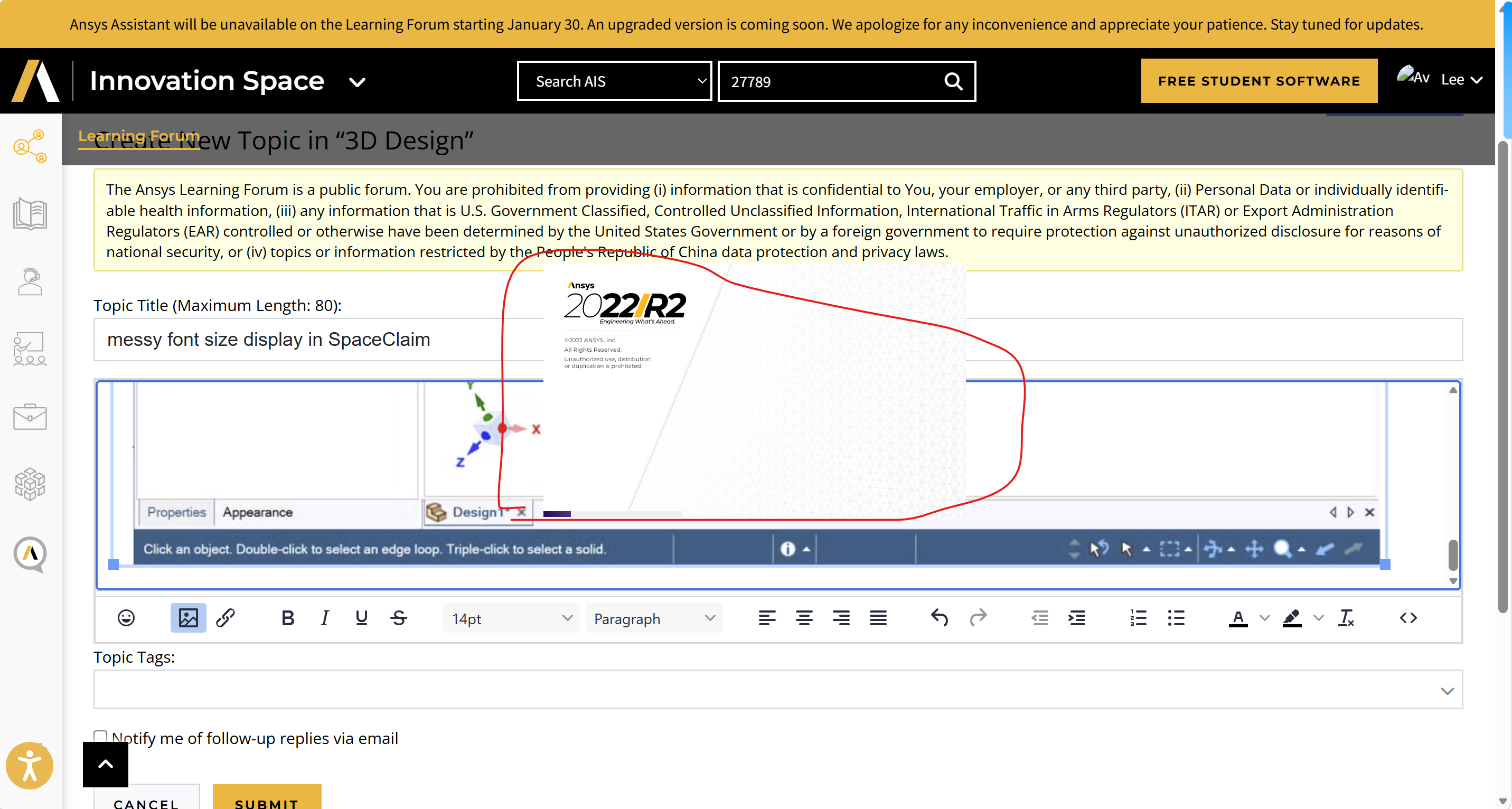 </p><p>
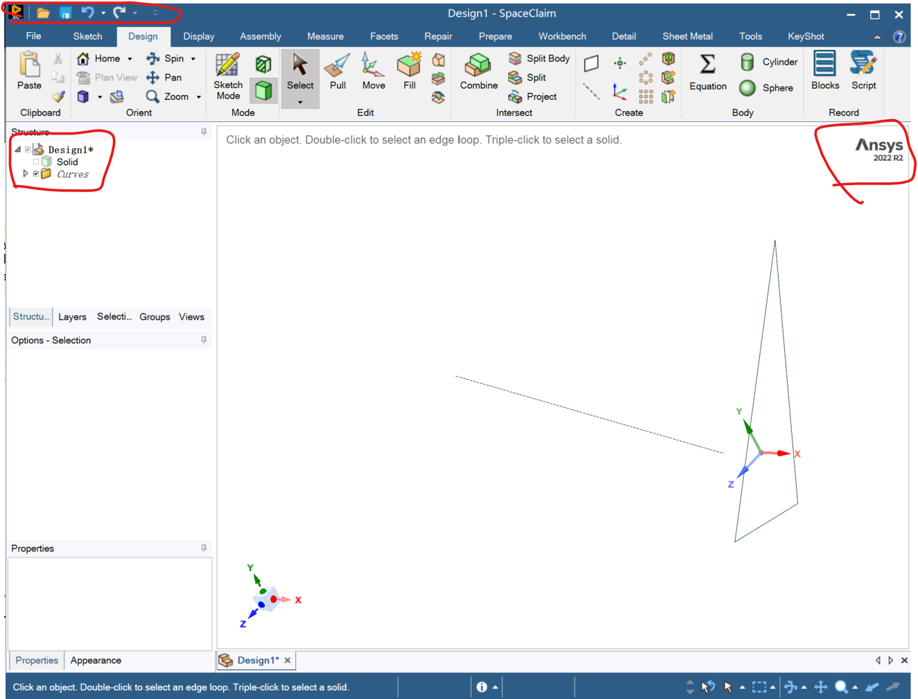 </p><p>While a normal state is shown like this. </p><p>
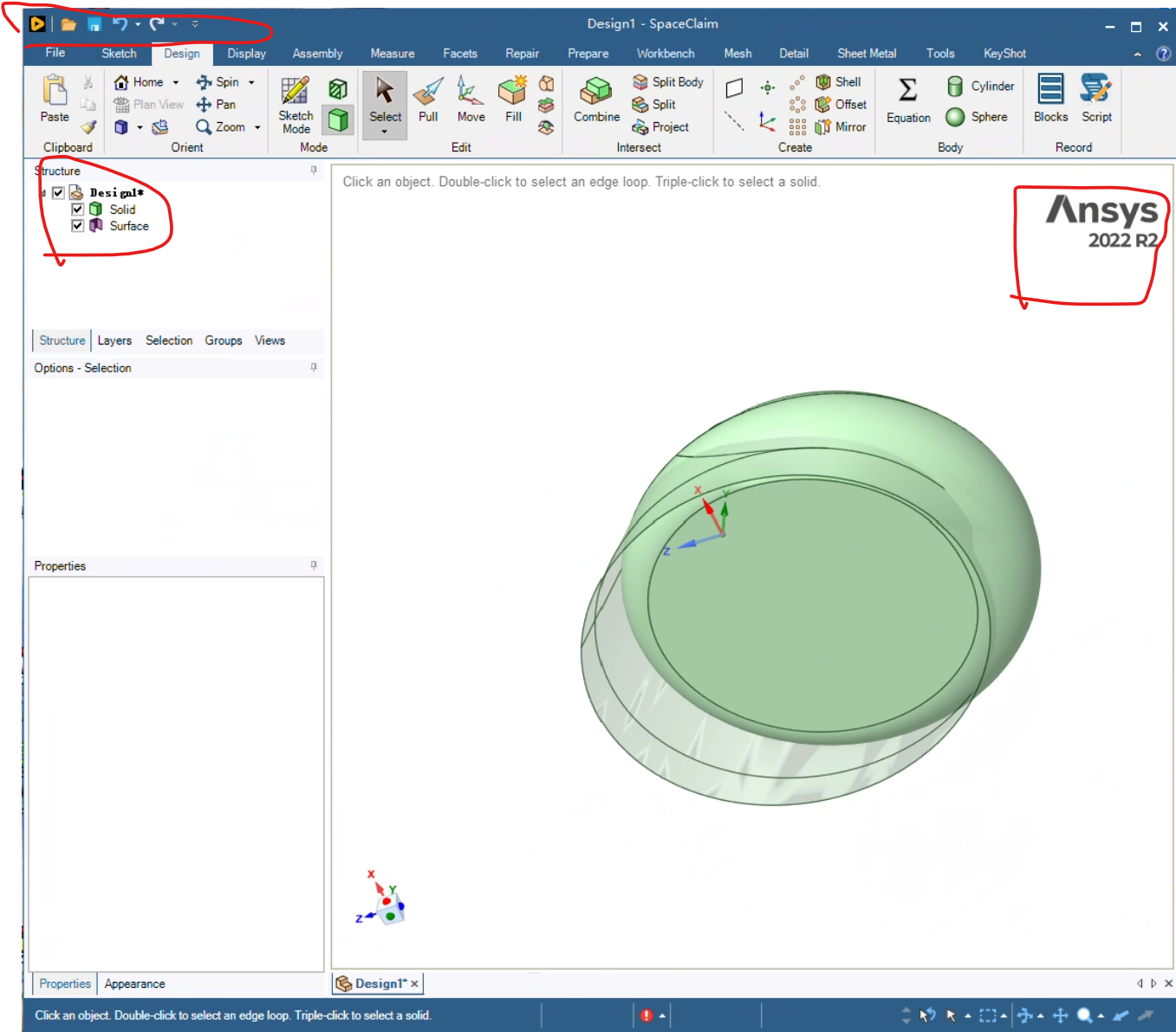 </p><p> </p><p> </p><p> </p></p><p> </p><p>Besides, I opened the Workbench and the user interface visualization is really a mess as shown below.</p><p>
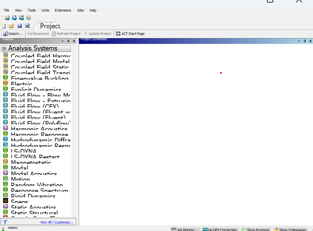 </p>
[topic_link] => https://innovationspace.ansys.com/forum/forums/topic/messy-font-size-display-in-spaceclaim/
[topic_status] => publish
[topic_published_date] => July 16, 2026
[author] => Dato
[like_count] => 0
[reply_count] => 3
[view_count] => 122
)
[8] => Array
(
[topic_id] => 461388
[topic_title] => Microstrip patch antenna
[topic_content] => <p>Design and Analysis of a Microstrip patch antenna for 5G Communication</p><p> </p>
[topic_link] => https://innovationspace.ansys.com/forum/forums/topic/microstrip-patch-antenna/
[topic_status] => publish
[topic_published_date] => July 15, 2026
[author] => naraincoolbudy123@gmail.com
[like_count] => 0
[reply_count] => 0
[view_count] => 137
)
[9] => Array
(
[topic_id] => 461387
[topic_title] => Discovery 2026 R1: Material assignment is persnickety and inconsistent
[topic_content] => <p>Two issues:<br>1) Upon startup with a new design, as a very first step: You can change the material from the default steel to some solid like aluminum, but if you try to assign a fluid like water or air, the interface does not respond and simply keeps the original solid. I can't seem to find an error message. <br>2) Again starting afresh, if you Design -> History Tracking -> Try and change the material:<br>You get two messages.
</p>
[topic_link] => https://innovationspace.ansys.com/forum/forums/topic/messy-font-size-display-in-spaceclaim/
[topic_status] => publish
[topic_published_date] => July 16, 2026
[author] => Dato
[like_count] => 0
[reply_count] => 3
[view_count] => 122
)
[8] => Array
(
[topic_id] => 461388
[topic_title] => Microstrip patch antenna
[topic_content] => <p>Design and Analysis of a Microstrip patch antenna for 5G Communication</p><p> </p>
[topic_link] => https://innovationspace.ansys.com/forum/forums/topic/microstrip-patch-antenna/
[topic_status] => publish
[topic_published_date] => July 15, 2026
[author] => naraincoolbudy123@gmail.com
[like_count] => 0
[reply_count] => 0
[view_count] => 137
)
[9] => Array
(
[topic_id] => 461387
[topic_title] => Discovery 2026 R1: Material assignment is persnickety and inconsistent
[topic_content] => <p>Two issues:<br>1) Upon startup with a new design, as a very first step: You can change the material from the default steel to some solid like aluminum, but if you try to assign a fluid like water or air, the interface does not respond and simply keeps the original solid. I can't seem to find an error message. <br>2) Again starting afresh, if you Design -> History Tracking -> Try and change the material:<br>You get two messages.  and
and 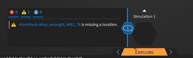 . <br>However, if you simply make a 3D object. Then you can change the material with history tracking still enabled. Clearly I changed the material with History Tracking enabled. You can also make it a fluid. <br>
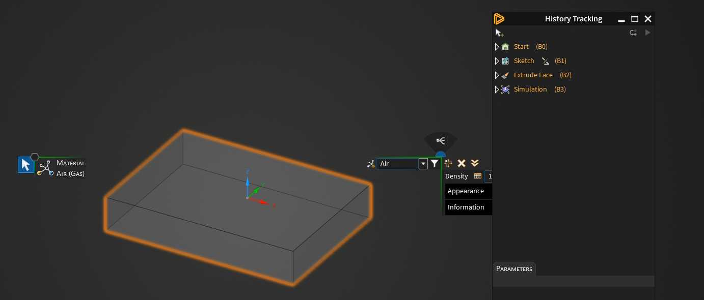 <br>Both of these seem like simple bugs. Or at a minimum an unnecesary constraint on a workflow. </p>
[topic_link] => https://innovationspace.ansys.com/forum/forums/topic/discovery-2026-r1-material-assignment-is-persnickety-and-inconsistent/
[topic_status] => publish
[topic_published_date] => July 15, 2026
[author] => pete
[like_count] => 0
[reply_count] => 1
[view_count] => 132
)
[10] => Array
(
[topic_id] => 461371
[topic_title] => 2D simulation
[topic_content] => <p>Hello Everyone,</p><p>Ansys Discovery allows creation of mid-surfaces for thin-walled structures, which are typically analyzed using shell elements. Since a mid-surface is essentially a 2D representation of a 3D solid with thickness assigned as a property, can Discovery perform a true 2D shell-based structural simulation? If yes, how are loads and supports applied, given that the software asks for face selections rather than edge selections on the mid-surface model.</p><p data-start="840" data-end="915">Any guidance, examples, or learning resources would be greatly appreciated.</p><p data-start="920" data-end="934"><strong data-start="920" data-end="934">Thank you</p>
[topic_link] => https://innovationspace.ansys.com/forum/forums/topic/2d-simulation/
[topic_status] => publish
[topic_published_date] => July 15, 2026
[author] => Bhargav.Bobbili-Int@cadfem.in
[like_count] => 1
[reply_count] => 2
[view_count] => 147
)
)
)
)
<br>Both of these seem like simple bugs. Or at a minimum an unnecesary constraint on a workflow. </p>
[topic_link] => https://innovationspace.ansys.com/forum/forums/topic/discovery-2026-r1-material-assignment-is-persnickety-and-inconsistent/
[topic_status] => publish
[topic_published_date] => July 15, 2026
[author] => pete
[like_count] => 0
[reply_count] => 1
[view_count] => 132
)
[10] => Array
(
[topic_id] => 461371
[topic_title] => 2D simulation
[topic_content] => <p>Hello Everyone,</p><p>Ansys Discovery allows creation of mid-surfaces for thin-walled structures, which are typically analyzed using shell elements. Since a mid-surface is essentially a 2D representation of a 3D solid with thickness assigned as a property, can Discovery perform a true 2D shell-based structural simulation? If yes, how are loads and supports applied, given that the software asks for face selections rather than edge selections on the mid-surface model.</p><p data-start="840" data-end="915">Any guidance, examples, or learning resources would be greatly appreciated.</p><p data-start="920" data-end="934"><strong data-start="920" data-end="934">Thank you</p>
[topic_link] => https://innovationspace.ansys.com/forum/forums/topic/2d-simulation/
[topic_status] => publish
[topic_published_date] => July 15, 2026
[author] => Bhargav.Bobbili-Int@cadfem.in
[like_count] => 1
[reply_count] => 2
[view_count] => 147
)
)
)
)

 You are navigating away from the AIS Discovery experience