
TAGGED: hexahedral-mesh, mesh, static-structural
-
-
April 11, 2022 at 5:41 pm
charlie_kc
SubscriberHi all,
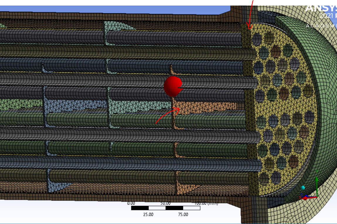
I have begun the modelling of a heat exchanger, using static structural analysis system. I've read online that hex mesh is preferred over tet, and so fortunately I have managed to apply hex mesh to the majority of the components (some required slicing to do so). However, my tubesheets and baffles [pictured] only appear to agree with the tet mesh ,which I am assuming is either to do with the thinness of the plates or the relatively uneven geometry (corners, holes etc).
Now my question is: is there any way to force these plates to adopt a hex mesh? And if not, will mixing tet and hex mesh across the various components greatly affect the accuracy of my solution?
Thank you in advance.
April 12, 2022 at 8:00 amAkshay Maniyar
Ansys Employee
Ansys employees are not allowed to download any files from forum. So can you please share the screenshots of the parts that you mentioned?
Thanks Amaniyar
Ansys Help
Ansys Learning Forum (Rules & Guidelines)
April 12, 2022 at 9:15 amVigneswaran Sridharan
Ansys EmployeeHey Linear tetrahedral/triangular elements suffer from three issues:
ÔÇÉThey have one integration point and are constant strain elements ÔÇô so we need an extremely fine mesh to capture the strain gradient accurately.
ÔÇÉ It's difficult to distort the element without changing its volume so theyÔÇÖre prone to volumetric locking for nearly or fully incompressible materials and maybe overly stiff.
ÔÇÉIn the case of bending-dominated problems, linear elements are also prone to shear locking which introduces spurious shear stresses in the part and make it overly stiff regardless of how fine the mesh is created.
Linear hexahedral elements, or the 8-noded hex elements, do not suffer from the first two issues, so they seem like a good alternative to linear tetrahedral elements, hence the general recommendation!
While it is a valid suggestion, it's not always possible to generate a hexahedral mesh. The above limitations are resolved by introducing mid-side nodes which creates a 10-noded tet element that uses second-order polynomial for shape functions. If the geometry is a combination of sweepable and irregular shapes in such then the combination of brick, tetrahedral, pyramid, or wedge elements is used. Pyramid elements are used in the transition regions.
Look at this relevant video on "Understanding importance of 3D element shapes and order"
Vigneswaran
Ansys Help
Rules & Guidelines ÔÇö Ansys Learning Forum
April 12, 2022 at 3:04 pmSubscriberHi Amaniyar I have tried to attach it now as a photo- are you able to see it?
April 12, 2022 at 3:17 pmAnsys Employee
Yes, I can see the image now. Thank you.
About the parts which you have highlighted, have you tried to use multizone method on this parts? I guess, multizone method will be useful for this parts.
Thank you for the detailed answer and course link. If it is not meshing in hex then you can use quadratic tetrahedral elements, as it will be less stiff compared to linear tetrahedral elements. You can go through the course which has shared for more details about the various elements.
Thanks Amaniyar
Ansys Help
Ansys Learning Forum (Rules & Guidelines)
April 12, 2022 at 3:58 pmSubscriberThank you very much for your detailed response. In order to add mid-surface nodes, does my component have to be a surface body as opposed to a solid body?
April 12, 2022 at 3:58 pmSubscriberThank you very much for your detailed response. In order to add mid-surface nodes, does my component have to be a surface body as opposed to a solid body? Doing some research based off your video, it looks like it may be best to convert the components to shell (using mid surface) as opposed to solid bodies, since they are relatively thin in comparison to the other dimensions.
April 13, 2022 at 9:38 amAnsys EmployeeHey You could also use Shell/3D surface elements (Like Shell181, Shell281) with mid-surface extraction in SpaceClaim (Refer to Midsurface tutorial (spaceclaim.com)).
But, keep in mind you cannot generate a Midsurface unless the faces have a constant wall thickness. In SC, the Midsurface tool will not select the non-parallel faces.
Nodes on Shell elements have 6 Dof's. Hence MPC based bonded contact should be used to connect shell and solid elements.
Refer to this video for more info on understanding shell elements.
Vigneswaran
Ansys Help
Rules & Guidelines ÔÇö Ansys Learning Forum
Viewing 7 reply threads- The topic ‘Meshing advice – tetrahedron to hex’ is closed to new replies.
Innovation Space Trending discussions
 Top Contributors
-
peteroznewman
 5824
5824 -
scabo
 1906
1906 -
Dennis Chen
 1420
1420 -
javat33489
 1305
1305 -
Shyam Prasad V Atri
1021
Top Rated Tags
© 2026 Copyright ANSYS, Inc. All rights reserved.
Ansys does not support the usage of unauthorized Ansys software. Please visit www.ansys.com to obtain an official distribution.
-


