-
-
March 25, 2022 at 10:54 am
tomas.monopoli
SubscriberI have a simple stripline over a dielectric in HFSS. I want to excite the line with a 1V source with impedance 50 Ohm. The termination of the stripline is also connected to a 50 Ohm impedance. I expect the voltage along the line to be around 0.5 V
From what I understand, setting incident voltage should be equal to setting the forward wave voltage, is that correct?
How can I set up a 1V source with an internal 50 Ohm impedance?
I tried adding port post-processing but I still obtain values around 1V.
Thank you
March 25, 2022 at 3:31 pmChinmay T
Forum Moderator
Please provide more details on how you are exciting the stripline and which port type you are using.
Can you share the screenshots of your simulation model?
Thanks Chinmay
March 25, 2022 at 7:44 pmtomas.monopoli
SubscriberOf course!!
I selected a terminal solution type.
I am using lumped ports.
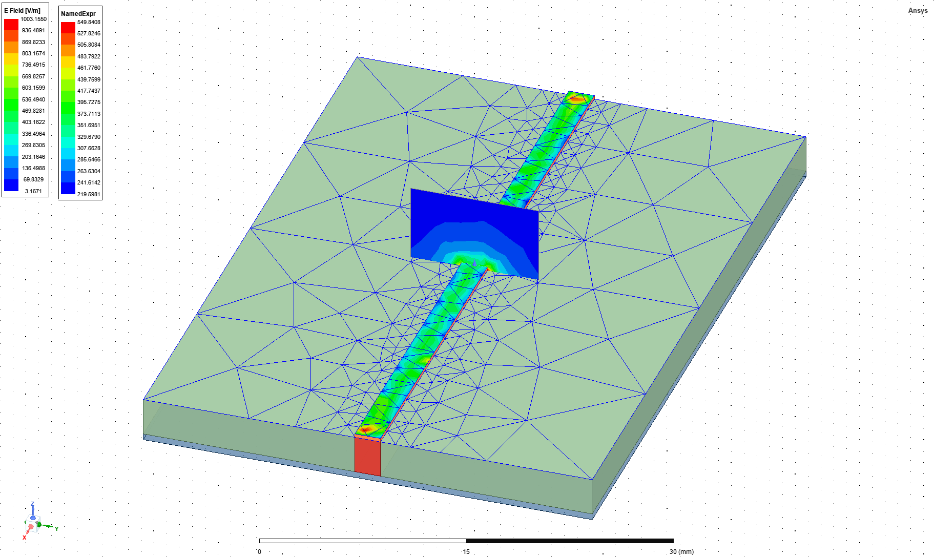
This is a screenshot of the design:

I think the problem is that I don't fully understand the excitation types:
I used Q2D to extract the characteristic impedance:
 As you can see the char impedance is quite different from 50 Ohms (that is the one I set to the lumped ports).
However, setting the sources to "incident voltage" I get a voltage across the line that is close to 1.
I believe this is quite strange, it should be close to 1 if the characteristic impedance were close the characteristic impedance of the port I think.
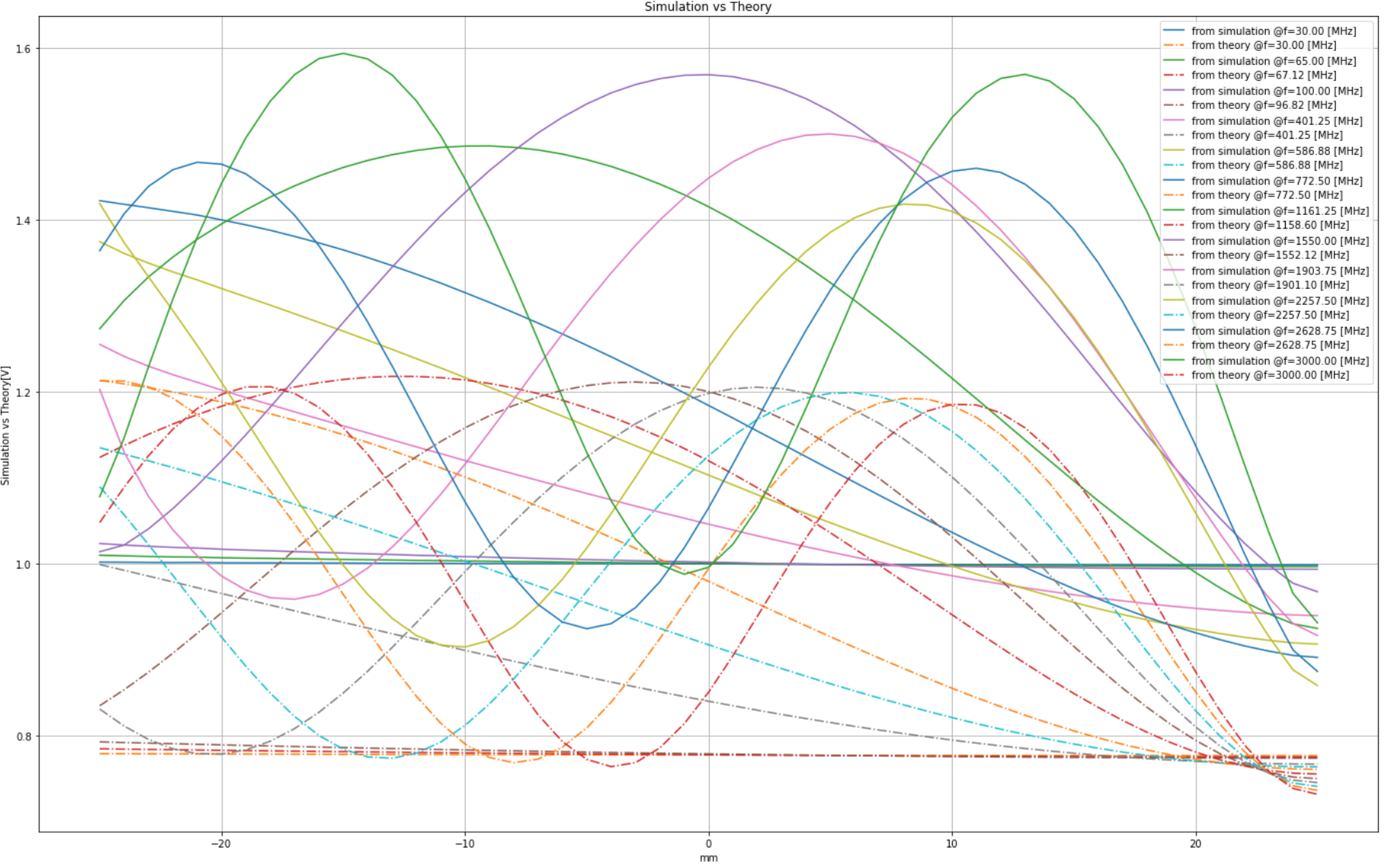
Here is a comparison with the transmission line formulas, where I set the forward wave voltage to 1:
 Thank you
Tomas
March 29, 2022 at 8:38 amChinmay T
Forum Moderator
You can directly see the impedance in HFSS design.
To plot the impedance,In the project manager window right mouse click on Results, go to terminal solution data report.
A new window pops up, in the category, select Terminal Port Zo and after this select quantity and function and click on a new report to see the impedance plot.
Thanks Chinmay
April 13, 2022 at 12:07 pmtomas.monopoli
SubscriberThank you both for your answers!
indeed, the impedance was set correctly and setting incident voltage to 1V is the same as setting the forward wave arriving to the port to 1V.
From the HFSS manual I read:
I(0)Zref = Vfw - Vbw and V(0) = Vfw+Vbw => 2Vfw = V(0)+I(0)Zref ; 2Vbw = V(0)-I(0)Zref;
Therefore if you want to create the classical voltage source with internal impedance Zo, you can set the incident voltage to Vs/2 and the port impedance to Zref = Zo.
Tomas
Viewing 4 reply threads- The topic ‘How to setup a voltage source with internal impedance in HFSS’ is closed to new replies.
Ansys Innovation SpaceTrending discussions- Y wiring method and the start and end points of winding.
- Lumped Port Deembed
- Hfss 3D pcb via capped and filled with epoxy
- Optimizing Via Impedance in Ansys HFSS 3D Layout Using Geometric Parameter Sweep
- AEDT Natural Convection with default correlation is failing solver initializatio
- HFSS libnvidia-ml.so too old or could not be found – Warning in slurm job output
- Three-Phase Voltage Imbalances in dual stator electric generator
- STL Import Errors in HFSS After Cleaning in SpaceClaim
- Calc Error in Field Calculator after PyAEDT Analyze
- import file autocad 3d
Top Contributors-
3862
-
1414
-
1220
-
1118
-
1015
Top Rated Tags© 2025 Copyright ANSYS, Inc. All rights reserved.
Ansys does not support the usage of unauthorized Ansys software. Please visit www.ansys.com to obtain an official distribution.
-


Ansys Assistant

Welcome to Ansys Assistant!
An AI-based virtual assistant for active Ansys Academic Customers. Please login using your university issued email address.
Hey there, you are quite inquisitive! You have hit your hourly question limit. Please retry after '10' minutes. For questions, please reach out to ansyslearn@ansys.com.
RETRY


