
TAGGED: constraint-issue, coordinates, displacement, remote-displacement, vertex
-
-
March 24, 2022 at 6:43 am
albin.linderstam
SubscriberHello,
How do I constraint a point using Displacement or Remote Displacement?
I want to constraint the origin of the coordinate system that I've created, so I select that coordinate system, but I still need to define a geometry. Even if I choose "Vertex" I cannot select that point.
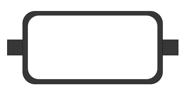
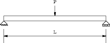
I kind of want to mimic the schematic loading condition below, but for a more complex part (which I cannot show completely).
March 24, 2022 at 7:18 amErKo
Ansys EmployeeHi
I would suggest to use beam elements for this since it is a beam bending situation - so define a line body for your geometry instead of a 3D part like you show above.
As for 3D solid parts like you show above, use the remote displacement to do what you need for 3D parts.
See this for more info:
All the best
Erik
March 24, 2022 at 9:42 amSubscriberThank you for your answer.
Okey, I haven't used beam elements before, but do that really work for a complex 3D-part?
I show my part schematically below:
 Regards, Albin
March 24, 2022 at 11:01 ampeteroznewman
SubscriberOpen the geometry in SpaceClaim and use two planes to slice the body at the center to create a vertex to use. On the Workbench tab, click the Share button to reconnect the four pieces in the Mesh. In Mechanical, when you select Vertex, there will be a vertex in the geometry for you to choose.
It is generally a bad idea to apply a displacement BC to a single node in a solid mesh because that creates a high stress since the reaction force has zero area. Instead of a vertex, you could project a small circle onto the outside face of the solid, then you would have a finite area that you could use to scope a Remote Displacement to.
If the geometry is a thin-walled container, you can use a midsurface operation in SpaceClaim to replace the solid container wall with a surface body. You can keep the solid ends and use Shared Topology to have the solid mesh connect with the shell elements on the container.
March 26, 2022 at 4:53 pmSubscriberYes, you are right, it is not preferable. The thing is that the more I tried to mimic the real situation, the stresses went more and more unrealistic.
I will try to explain the situation step by step and in more detail. I will also use this example as a basis to ask some more general FEA-questions, hope that is okey!
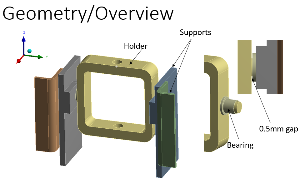
The geometry (simplified model compared to reality since I'm not allowed to show the 3d-model):
Components: Holder, inner support (2x), outer support (2x), bearing (2x)
The bearing is press-fitted into inner support
The cylindrical ends of the Holder can slide with low friction inside the bearing
There is a small gap between the flange of the Bearing and the Holder
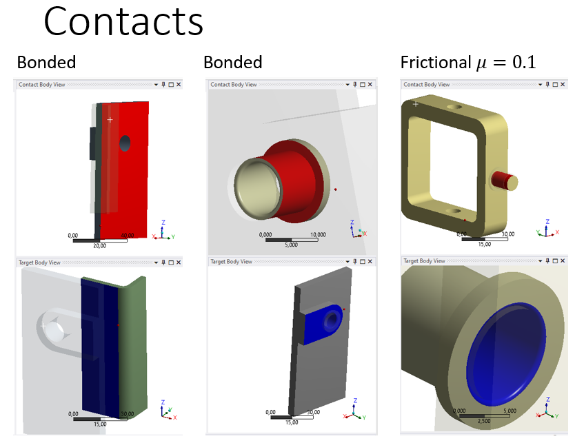
 The connections:
Bonded surface between inner and outer support
Bonded surface between bearing and inner support due to press-fitting. The surface of the flange should perhaps not be bonded, but do not think it affects the results so much
Low friction between the cylindrical ends of the Holder and the inside surface of the bearings
 Here I can say that in my first analysis I simulated the low friction as Frictionless Contact because I thought it was more computational friendly than Frictional so I wanted to use that as a first simplification, until my colleague said that Frictional Contact is more easy to solve for Ansys to prevent Rigid motions. Q1. Is Frictional Contact more computational friendly than Frictionless Contact? When do we even want to model Frictionless Contact?
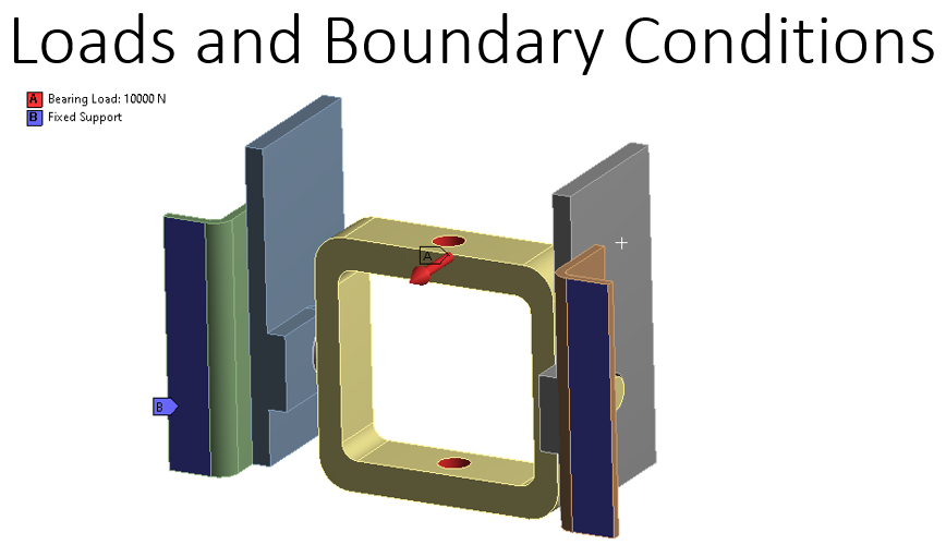
The loads and boundary conditions are first modelled as:
Bearing loads applied to the centrum holes of the Holder
Fixed Support to the ends of the outer supports
 Results:
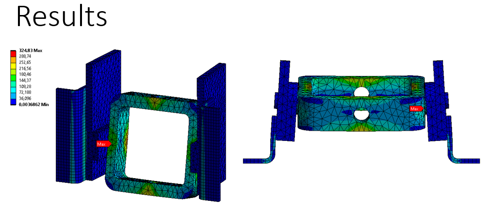 In reality there are pins inside the centrum holes of the Holder, hence I don't think the centrum holes can rotate around Y-axis.
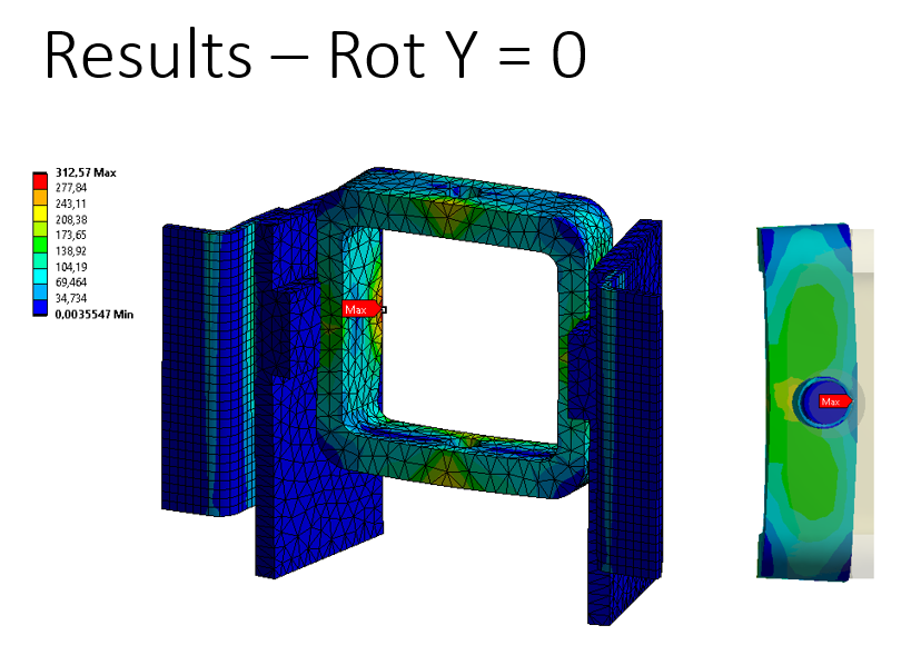
Q2. Is it correct to apply a Remote Displacement to centrum hole surfaces and set Rot Y=0? The reason for my uncertainty is all the discussions of Displacement vs Remote Displacement and 3 DOFs vs 6 DOFs. Since 3D-elements only have 3 DOFs (Ux,Uy,Uz), I'm not sure it makes a difference.
However, according to the results below, it seems that it stabalizes the Holder and not make it rotate so much around Y-axis, but it still has rotated a little bit. Not sure how to interpret this little rotation. Q3. If Rotation is not applicable to 3D-elements, why where the results changed?
 A third approach could be to add a pin going through both holes and apply the Bearing Load to that pin and add Displacement Uz=0 to top/bottom of the pin to prevent Rotation around Y-axis. Q4. Is this a reasonable approach? I would prefer not to add more components since it would mean more elements and longer computational times, but it seems pretty straight forward. Currently using frictional contact between pin and holder (mu=0.1), but perhaps frictionless contact is better here?
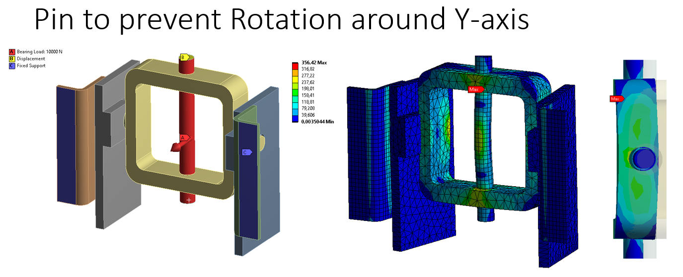 From this solution, there is still a little rotation, I assume it depends on the distance between the cylindrical holes and the Displacement Uy=0.
March 26, 2022 at 4:55 pmSubscriberContinuation due to many characters:
Regarding computational time, since my geometry is much more complex than in this model, I tried to only half of the model due to symmetry.
Q5. I have not yet used the built-in Symmetry-function, instead I simply applied Frictionless Support to the split section, which I read is equivalent to the Symmetry-function. Is Frictionless Support equal to using a Displacement and set Normal direction Uy=0 as well? Or is it only equal when using 3D-elements and otherwise rotations need to be set to zero using as well using Remote Displacement? Nevertheless, I assume that Frictionsless support is the approach to mirror symmetry conditons. (/forum/discussion/29022/replicate-symmetry-with-nodal-displacement)
So here is a result from the Symmetry, using a Pin to avoid rotation around Y-axis, frictionless support on the splitted surface and only half of the load:
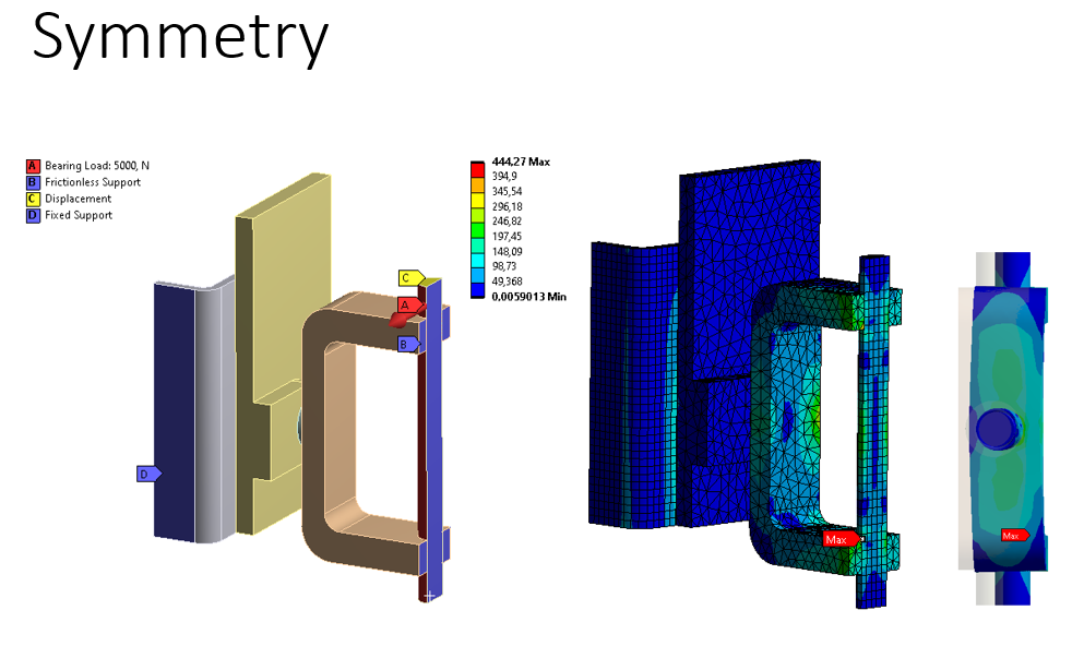 Q6. Do you know why the stresses are higher compared to the case above? I could assume a slight difference, but not 444 vs 356 MPa. I've checked contacts and it seems to be the same.
Sorry for a lot of questions..! Really appreciate your help ! Kind regards, Albin
March 26, 2022 at 5:52 pmSubscriberDear Albin Thank you for the questions that have very good images to support them.
Q1. Yes, it takes a little more computation to include friction, but not a lot more. If a body has no connection to ground other than contact, then Frictional Contact is often helpful and sometimes required for the solver to converge. In the situations where the solver can converge with Frictionless Contact, an engineer might want to include the limits of friction in a design study to document the change in results from maximum coefficient of friction to zero friction.
Q2. It would be valid to scope a Remote Displacement to the two centrum hole surfaces and set Rot Y = 0 as long as the Behavior = Deformable is used, which is the default. This will prevent rotation of the holder without adding any extra stiffness to the holder. The constraint is being applied to a pilot node at the center of the holder. That node has 6 DOF and represents the average motion of all the nodes it is scoped to, which are the nodes on the two holes. It doesn't matter that those nodes only have 3 DOF.
Q3. The average motion of all the nodes in the two holes is represented at the pilot node at the centroid, which had a zero rotation about the Y axis. The results changed because without the Remote Displacement, there was a small moment about the axis and it caused some rotation.
Q4. I don't think adding a pin is necessary. Use the Remote Displacement approach.
Q5. For solid elements, a Frictionless Support is equivalent to using a Displacement and setting just the normal direction to 0, which is equivalent to inserting a Symmetry branch into the outline and inserting a Symmetry region under that branch. The benefit of using a Symmetry object is that you can create a visual representation of the full model because the post processor can reflect the results if you want.
For shell models, Frictionless Support is not the same as Symmetry. Don't use Remote Displacement to hold the rotations in the two axes of the symmetry plane, use Fixed Rotations which act on individual nodes without a pilot node, or insert a Symmetry Object and a Symmetry Region and that will do all you need.
Q6. The symmetry model has higher stress than the full model because the elements are smaller in the symmetry model.
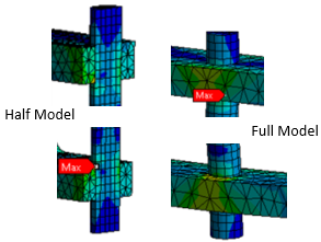 One task that analysts do is perform a mesh refinement study which attempts to find a "mesh independent" result. If you take either the half or the full model and plot maximum stress in one part at one location versus element size, you hope to see a plot that levels out to a constant stress as the elements get smaller and smaller. That constant stress is the true solution.
Unfortunately, many models contain a mathematically infinite stress which is called a singularity. An example is a perfectly sharp interior corner, which doesn't exist in reality, but is easily made in a simulation model. As the element size gets smaller and smaller, the stress gets larger and larger, without limit.
Best regards, Peter
March 27, 2022 at 12:00 pmSubscriberThank you very much for your input Peter, incredible as always. Sometimes it can hard to find answers for Ansys-problems in general, but your input to a lot of discussion on this forum solves a lot of problems. To be honest you should share your knowledge on a Youtube-channel or a website. Would be great ´╗┐ƒæì´©Å´╗┐
I have some questions based on your answers, hope you don't mind. Been searching a bit but not been able to find answers.
Q2. Regarding "It would be valid to scope a Remote Displacement to the two centrum hole surfaces and set Rot Y = 0 as long as the Behavior = Deformable is used, which is the default. This will prevent rotation of the holder without adding any extra stiffness to the holder. The constraint is being applied to a pilot node at the center of the holder."
Q3. "The average motion of all the nodes in the two holes is represented at the pilot node at the centroid, which had a zero rotation about the Y axis."
Q11. Perhaps I misunderstood you, but is the Remote Displacement that I already applied correct then? Even though there were small rotations of the surface around the hole? (I applied a common Remote Displacement for both hole surfaces)
Q22. Do I need to add Remote Points to apply Remote Displacement to the centrum of the hole surfaces? I assume no based on: "Search this site for Remote Force and Remote Displacement. These use Remote Points without manually creating them. That is done "under-the-hood". (/forum/discussion/24974/what-is-a-remote-point-in-ansys)
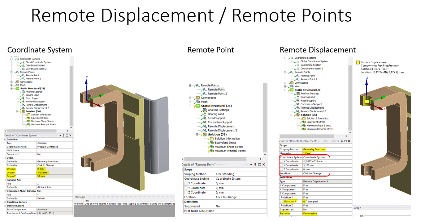
Regardless, I added a Coordinate System to one of the holes and a Remote Point at the origin of that Coordinate system (Did not know how else to add a Remote Point to the center of a hole)
Regarding the Remote Displacement, here I am a bit unsure:
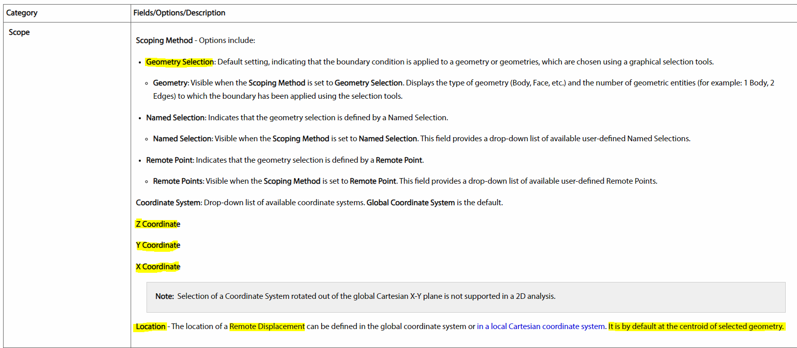
Q33. The coordinates that appear (X, Y, Z Coordinate), is that the coordinates of the Remote Point or Pilot node (could not see description in mechanical user guide below)? If yes, why is it not the same as the coordinates of the Coordinate System (0, -40.5, 35)? The coordinates does not change regardless of the Coordinate System I select, so I assume that they relative to the selected geometry somehow?
Location - I assume that I do not need to touch this (based on info from mechanical user guide below)
Q44. According to mechanical user guide below, "It is by default the centroid of selected geometry" - So do I need to do anything special besides selecting the surface and set Rot Y = 0? Which I already did (Pretty much same question as Q11)
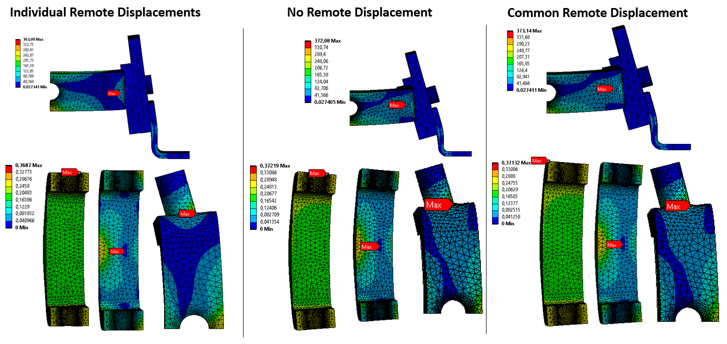
Q55. Is the result the same if I apply one Remote Displacement to hole 1 and another to hole 2 than using one Remote Displacement for both holes? I noticed that the Coordinates will be placed in either holes or in the center between the holes. I did some laboration in the third image below. It seems that the result differ if I apply a common Remote Displacement for both surfaces or if I apply them individually. The common Remote Displacement look more similar to no Remote Displacement at all.
 Q66. So by using the symmetry branch, I don't need to split my models before importing to Ansys?
Q77. Regarding "One task that analysts do is perform a mesh refinement study which attempts to find a "mesh independent" result. If you take either the half or the full model and plot maximum stress in one part at one location versus element size, you hope to see a plot that levels out to a constant stress as the elements get smaller and smaller. That constant stress is the true solution.", do you have any tips or recommendations about this? I think I saw you refer to a thread about this in another discussion, but it was broken if I remember correctly (/forum/discussion/935/mesh-convergence-study "Here is my post onMesh Convergence Studywhen using linear elastic materials.") Just not sure how to plot maximum stress at the same location during different solutions with different mesh sizes.
Again, thank you for your time!
Regards, Albin
March 27, 2022 at 1:40 pmSubscriberI do share my knowledge on a YouTube channel. https://www.youtube.com/channel/UC0cffQ4Ccz5MA6LefcdBPZg/videos That is where I store the videos I use to answer questions on this forum. When the forum was converted to a new platform, some of my best discussions were lost. Fortunately, I can still help students who ask the same question by pointing them to a video, even though the link to the old discussion is broken. My most popular video has nearly 20k views, but the discussion it supported was lost over a year ago.
Q11. For a Remote Displacement scoped to both the top and bottom holes, there will be a pilot node at the center of the frame, between the two holes. The nodes around the top hole will move approximately as a group while the nodes around the bottom hole will move approximately as a separate group. Now if the top group rotates 2 degrees about Y, while the bottom group rotates -2 degrees about Y, the average rotation of all the nodes is 0. That is what the Remote Displacement is enforcing.
Q22. When you create a Remote Displacement (or Force), a Remote Point is automatically created under-the-hood. You can expose visibility to that by right click on the Remote Displacement and select Promote to Remote Point. You would do this if you wanted to reuse the Remote point, such as to apply a force as well as the displacement that you wanted. By default, a Remote object will use the Global coordinate system but you can specify any Cartesian coordinate system you create to control the loads or supports at the pilot node.
Q33. The location of the Remote Point/Pilot Node (whether under-the-hood or manually) is created at the centroid of the scoped geometry and listed in Global Coordinates. If you change the Coordinate System, the location X, Y, Z values DO NOT CHANGE to keep the point at the same location in space. I wish it would as I expect many people assume it would do that. You have to be very careful when changing the Coordinate System for a Remote Point to update the X, Y, Z values of the location to be exactly what you want. See the example in Q44. Another way to get unexpected locations in a Remote object is if you have created a first object, say for the top hole, and then you use Duplicate on the object in the Outline and scope the second duplicated object to the bottom hole. When you rescope an existing Remote object to new geometry, the location field DOES NOT UPDATE. That is why I never duplicate Remote objects in the Outline. I always create each one independently so that each one has the pilot node at the centroid of the scoped geometry.
Q44. The location of the Remote Point (whether under-the-hood or manually) is created at the centroid of the scoped geometry. You can adjust the coordinates by typing in new values. An example of when you would want to move the default location is when you have a long cantilever beam with a tip force. The cantilever has been split into two pieces: the tip and the base. There is a coordinate system at the tip, but the tip body is suppressed. The load enters at the split face where the remote point was created but you want the Force at the tip, so you change to the coordinate system at the tip then type 0,0,0 for the location. Now the force at the tip will be converted to a set of nodal forces that create the force and bending moment at the split plane. You don't need another coordinate system if you know the global coordinates for the location of the tip force. In your case, you don't need a special coordinate system.
Q55. If you use two Remote Displacements and each one has a pilot node at the center of each hole, you will enforce that the top group of nodes has an average rotation of 0, not the 2 degrees you got in Q11 and the bottom group of nodes will have an average rotation of 0 degrees, not the -2 degrees you got in Q11. So the stress results will be different. The setup of Q11 is more similar to no remote displacement, which allows each group of nodes to rotate, but in equal and opposite amounts.
Q66. You must split the geometry in CAD or SC before you bring it in to apply a Symmetry Region.
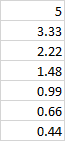
Q77. Once you observe that the maximum stress is on one face of the model, you can add a Von Mises Equivalent Stress output and scope it to that face. On the Details window for that output is a Results category and a square next to the Maximum value. Click that square and you will get a P for Parameter. The Workbench schematic will now have a Parameter Set box with an Output. Insert a Sizing Mesh Control on that face with a specified element size of 5 mm. Click the square to get a P for the element size. The Parameter Set box will now have an Input. In Workbench, open the Parameter Set box and type a series of smaller and smaller values in the Element Size column in the Table of Design Points. The best practice is to use a fixed ratio for the size where the ratio is between 1.2 and 2. It looks like an element size of 5 mm puts 2 elements across the thickness of the frame so using a ratio of 1.5, in the Table of Design Points, type in the seven rows below for the element size.
 Click the Update All Design Points button and go away for a break. Workbench will automatically solve the model seven times and fill out the Maximum Stress in the output column. Copy the table and plot the values in Excel. If the stress value is converging on a fixed value as the element size tends toward zero, then you have your True Stress result. If the stress value keeps increasing, then this face includes a singularity and the geometry will need to be refined to get rid of that.
Regards, Peter
March 27, 2022 at 1:59 pmSubscriberThank you very much for your answer . I was preparing a new post at the same time you answered so I post this before getting in too much detail of your answer above. I will look into in more detail later on I tried to apply the loadings and contacts from our discussion to the real problem, but I get a lot of warnings and errors:
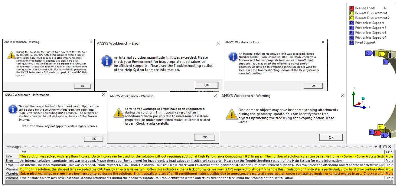 Sorry I cannot show complete model, but its mainly just more complex geometries (fillets, chamfers etc.) and same Contacts as described above. The Loadings and Boundary Conditions can be seen in the figure above, where the Fixed Support is applied to the outer support outside the image (Note that in this model the coordinate system has different orientation than in the example above (*)). I'm not sure it makes any difference, but I applied all the Frictionless Supports and Remote Displacements one by one instead of together. So regarding Q55, it seems that it is more accurate that I apply individual Remote Diplacements? Since you say that Q11 is more similar to not having any Remote Displacement at all.
Regarding the Node 600462, where Uy(*) is problematic, I cannot find it. It tried Preferences -> Node Numbers -> 600461-600463, but I cannot find them.
March 27, 2022 at 2:14 pmSubscriberSomething in your full model is not properly constrained. The diagnostic technique to find the cause of the problem is to drop a Modal analysis on the Model cell of the Static Structural analysis. Now drag all the support boundary conditions from the Static Structural category to the Modal category in the Outline. Set the Modal Analysis Settings to deliver 12 modes. Solve the Modal analysis then plot Deformation for all the modes. If you get six modes with almost 0 frequency, that is a body that is unconnected to ground.
The most accurate model is to add the pin and make contact in the holes. That is the true behavior of the motion of the nodes in each hole. The flexing will cause more pressure to be on the inner circles of the holes and less or no pressure on the outer circles of the holes.
March 28, 2022 at 8:41 amSubscriberYes, that certainly feels like the case. I haven't tried the diagnostic technique with Modal Analysis yet. Q8. Will it show me where it is not connected correctly or simply a input good/bad, based on "six modes with almost 0 freq."?
I added pins for contact in the holes and I can make the model work if I only use Linear Contacts (Bonded or No Separation), but that does not feel very realistic. As I insert Frictionless or Frictional Contacts, the model cannot find a solution since I get the following error:
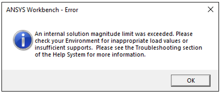 I tried to follow the diagnostic technique according to this article: https://mechanicalland.com/ansys-an-internal-solution-magnitude-limit-was-exceeded-error-solution/ , but still I got the same error so I was not able to see the solution and identify the problem. According to the comments, other people have tried this solution without making it work. Q9. Do you know why?
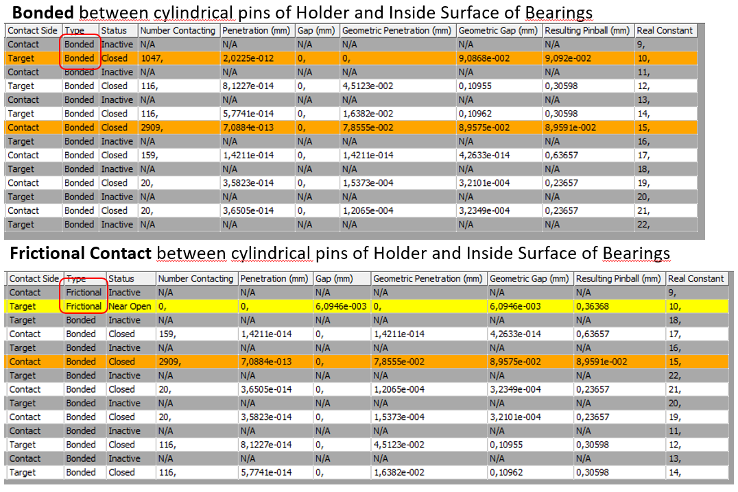
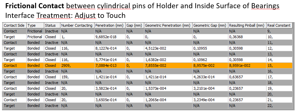
Regardless, it seems that the problem is due to Contacts if I'm not wrong (since the model can run with linear contacts only). I noticed that you wrote in another discussion (/forum/discussion/30522/error-an-internal-solution-magnitude-limit-was-exceeded) with the same Error message that "Whenever you do Frictional Contact, you must insert a Contact Tool and make sure all the contacts are closed". So I followed a tutorial based regarding the Contact Tool (https://www.youtube.com/watch?v=6AcHVLuL7Z8) and this is the result:
If I only have bonded contacts everywhere vs if I have a frictional contact
 Yello: This contact status is open. This may be acceptable
Not sure how to interpret the values here (haven't used Contact Tool before):
Q10. Number Contacts "N/A" on some?
Q11. Should I really have Penetration? Isn't that prevented with Contacts? Or is it a small Penetration due to Coarse mesh perhaps?
Q12. Difference between Penetration and Geometric Penetration?
Q13. Difference between Gap and Geometric Gap?
Q14. I noticed now that the Inside Diameter of the Bearing is 0.006mm larger than the Cylindrical pin of the Holder, is this something that I need to change, so the diameter is the same? Or can I change "Interface Treatment" to "Adjust to Touch" instead? (/forum/discussion/30522/error-an-internal-solution-magnitude-limit-was-exceeded)
When I change to "Adjust to Touch" I only get the wollowing messages (i.e. no errors):
 And Contact Tool now states:
 Q15. I noticed that the outside diameter of the Bearing is 0.002mm larger than the inside diameter of the hole in the Inner Support (due to press-fit). Do I need to change the CAD-models here so that d=D or is this considered by the Bonded Contact so that I don't need to worry about penetration here?
Q16. Since it hard for me to find a Solution using Non-linear contatcs, could it be a good idea to add Weak Springs? Or when should I consider using Weak Springs in general?
Sorry again for a lot of questions.
March 28, 2022 at 12:10 pmSubscriberRegarding the Node 600462, it may be a pilot node created by the solver that is not visible in Workbench.
Q8. A Modal analysis will show, for each mode, the component name that has the maximum deformation and the animation will show that piece moving, so it is very useful to diagnose which part is the problem. However, Modal is a Linear analysis and will automatically convert all nonlinear contacts to linear contacts (Bonded or No Separation). So if the problem in Static Structural that prevents convergence is a nonlinear contact, the Modal analysis might not show the source of the problem.
Q9. I don't use the method of turning off Solver Pivot Checking to diagnose failures of Static Structural to solve. I go to the Modal analysis technique.
Q10. Contacts have a pair of faces that are assigned the role of Contact or Target. You can flip the assignment of the two roles. There are reasons for choosing one assignment vs flipping them. The Program Controlled setting allows the solver to choose. The one it didn't choose is Inactive. Those are the rows with N/A for Number Contacting. Just ignore all the rows labeled Inactive. The simple way to do that is click on the Status column and all the Inactive rows will be put together.
Q11. Small penetration (or gap) on Bonded Contacts is acceptable and makes no difference because the faces will be bonded at their current configuration. A small penetration on a Frictional Contact will be resolved during the solution unless Adjust to Touch is used to remove the small penetration.
Q12 & 13. I only look at Penetration and Gap. I don't know how they define Geometric versions of those. Maybe something to do with Geometric Modifications?
Q14. Do you mean you measured the parts in CAD and found the 0.006 mm larger hole than pin? If your model relies on Frictional Contact to have a component be connected to ground, then the contact must be closed. If there is a small gap, then use Adjust to Touch to close the gap.
Q15. See answer to Q11.
Q16. You can turn on Weak Springs if the solution does not initially converge, but it is generally not needed once all the problems are fixed. One example of a problem is having a frictional contact, such as the pin in a hole. Assuming the contact is closed, there is one more thing to do. Under Analysis Settings change Auto Time Stepping to On with Initial Substeps set to a large number such as 100. These settings allow the contact to be established when only 1% of the load is applied. The default is to apply 100% of the load but the pin may get pushed past the surface of the hole before the contact had a chance to develop. If you had Weak Springs On where you didn't edit the Analysis Settings, you might see the pin about a meter away from the hole, so you still have to go back and fix that problem.
If you have a pin in a larger diameter hole, even if it is tangent to the side of the hole you want to push against, it has the freedom to roll around. This motion can prevent the solver from converging. Weak Springs could prevent this failure to converge. Instead of Weak Springs, it would be better to add a Remote Displacement on the pin that fixes rotation about the axis of the pin to allow the solver to converge. If you have a symmetry plane and a half model, the pin can't roll.
March 30, 2022 at 12:18 pmSubscriber, thank you so much for all your answers!
I did a comparison between Symmetry Region and Frictionless Support on split faces.
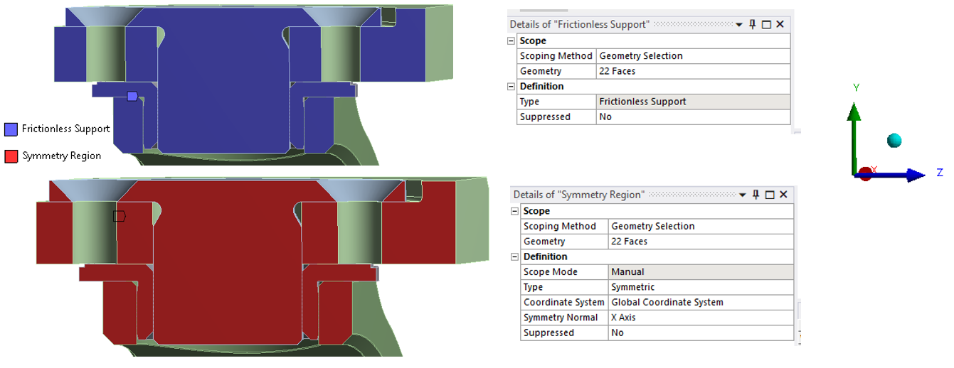 When I used Symmetry Region, i pretty much received twice the stress compared to Frictionless Support.
Perhaps there is so setting inside the Symmetry Region that I miss, but the Normal Direction was correct so I don't know what was wrong (see image above).
I should add that the values from using the Frictionless Support was more realistic and was close to values modelling the whole assembly. I can also add that when I used Symmetry, I received the following warning message, hence it seems that it is not constrained correctly using Symmetry Region:
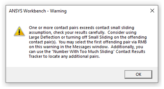 I can add that this contact is between the Bearing and the cylindrical end of the holder, which slide in X-direction.
Do you have any idea what can be wrong here? I cannot show complete model and results unfortunately, but I hope the answer is within the settings.
Regardless if I run with Symmetry or Frictionless Support, I received this message as well:
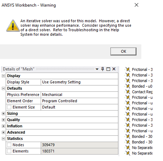 I've tried to find answers regarding this, advantages/disadvantages etc. I have a lot of nodes and also non-linear contacts, so perhaps direct solver could speed up the process a bit? Do you have any tips/input about this?
March 30, 2022 at 6:24 pmSubscriberVery interesting results. I will write a longer reply later today.
March 30, 2022 at 6:54 pmSubscriberThank you!
I think that I applied half the force in one of the cases.. :/ So perhaps that's solved.
March 30, 2022 at 7:00 pmSubscriberOkay, more later.
Viewing 16 reply threads- The topic ‘Constraint a point / coordinate’ is closed to new replies.
Innovation Space Trending discussions
 Top Contributors
-
peteroznewman
 6284
6284 -
scabo
 1906
1906 -
Dennis Chen
 1457
1457 -
javat33489
 1308
1308 -
Shyam Prasad V Atri
1022
Top Rated Tags
© 2026 Copyright ANSYS, Inc. All rights reserved.
Ansys does not support the usage of unauthorized Ansys software. Please visit www.ansys.com to obtain an official distribution.
-


The Ansys Learning Forum is a public forum. You are prohibited from providing (i) information that is confidential to You, your employer, or any third party, (ii) Personal Data or individually identifiable health information, (iii) any information that is U.S. Government Classified, Controlled Unclassified Information, International Traffic in Arms Regulators (ITAR) or Export Administration Regulators (EAR) controlled or otherwise have been determined by the United States Government or by a foreign government to require protection against unauthorized disclosure for reasons of national security, or (iv) topics or information restricted by the People's Republic of China data protection and privacy laws.
